> What’s New ? <
Blinky-1a.fs
Version 5183fa45
Intro
blinky-1a.fs blinks the green led on GPIOC-9, it’s the simplest of ‘blinkies’ written purely with hexadecimal “magic numbers”, no labels.
Later modules will show how to use CMSIS-SVD labels to make the source readable and maintainable.
Hardware
STM32F0 Discovery board
Blinky-1a
Blinky-1a.fs is the simplest blinky because there are no DEPENDENCIES, everything Forth needs for this blinky is in this one file. There are no include files, distractions, abstractions or extra complexities used here.
Embedded source like this is perfect for the MCU, but the “Magic Numbers” make it unreadable and unmaintainable by people. To understand them, the source must first be decoded by the reader using the STM RM0091 Reference manual for STM32F0x1/STM32F0x2/STM32F0x8 advanced ARM®-based 32-bit MCUs. This is a very slow and tedious process; examples of “Magic Number” use are lines 7 - 12, 15, 21 and 24 in the blinky-1a sourceode below.
Ideally, good Forth embedded source should use descriptive Word names, for instance it’s not hard to figure out what the “green-led.on” Word does is it?
In the next module using labels to make Forth source readable and maintainable will be discussed.
Warning
Cortex-M chips boot up with all peripherals DISABLED except the debugging and SWD. This is so the power saving capability of Cortex-M is fully utilised. Mecrisp-Stellaris (serial terminal) enables GPIO’s A,B,C,D and F by default.
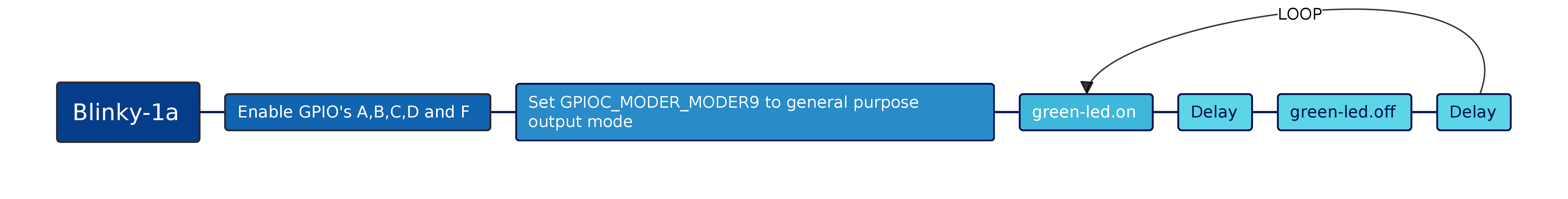
This blinky-1a flowchart was created using the *outstanding FLOSS mindmapper software https://docs.freeplane.org/*
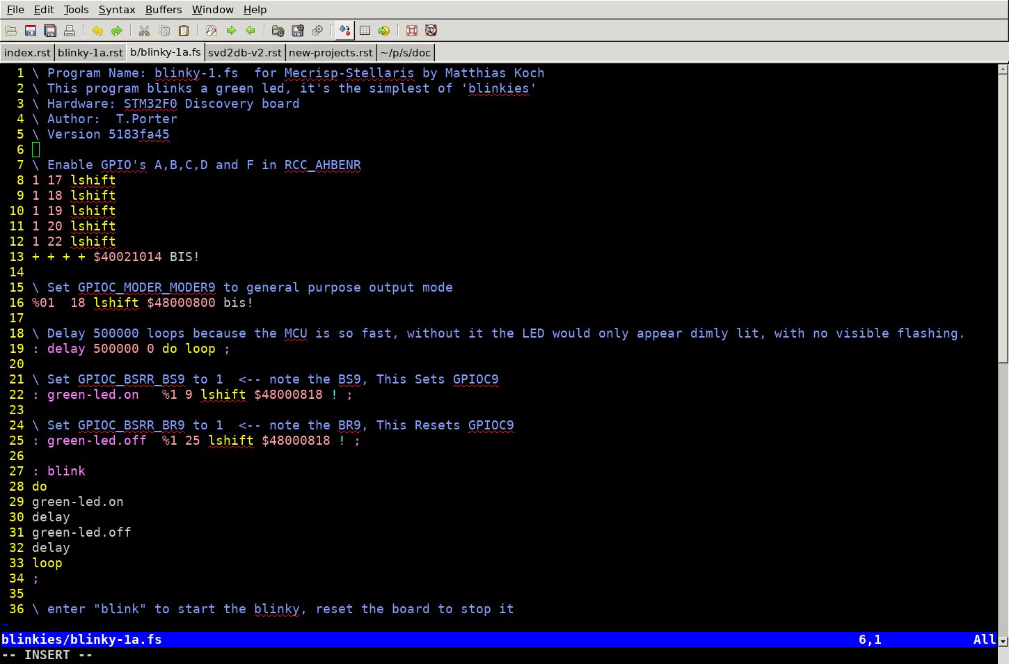
blinky-1a sourceode
How The Source Was Made
Information from the STM RM0091 Reference manual for STM32F0x1/STM32F0x2/STM32F0x8 advanced ARM®-based 32-bit MCUs was used to obtain the necessary technical knowledge to write the blinky-1a source.
Bitfield information and Register absolute hex addresses were obtained using the search facility of readdb, the database reader of SVD2DB-V2.
Code was written using the VIM-GTK editor (see pic above) which has Forth syntax highlighting for *.fs files.
Blinky-1a Operation
Lines 7 - 12
See also
STM32F051 Reference Manual RM0091 “AHB peripheral clock enable register (RCC_AHBENR)”
Find the bitfield BitOffsets and bitWidths for Register RCC_AHBENR, Bitfield IOP*EN to ENABLE the GPIO Peripherals. Also find the memory address for Register RCC_AHBENR
% ./readdb -p rcc -b IOP -T | grep EN

name                            address     ar  bw  bo  description
------------------------------  ----------  --  --  --  -------------------------
RCC_AHBENR_IOPAEN               $40021014   rw  1   17  I/O port A clock enable
RCC_AHBENR_IOPBEN               $40021014   rw  1   18  I/O port B clock enable
RCC_AHBENR_IOPCEN               $40021014   rw  1   19  I/O port C clock enable
RCC_AHBENR_IOPDEN               $40021014   rw  1   20  I/O port D clock enable
RCC_AHBENR_IOPFEN               $40021014   rw  1   22  I/O port F clock enable
See how it works ?
With any Cortex-M MCU all the MCU information is supplied in CMSIS-SVD files and SVD2DB extracts all this into a database for readdb to search.
Basically every Bitfield is configured by using the BitWidth and BitOffset values as input parameters for a Left Shift (lshift). Multiple configs may be added together and then saved to the relevant Register using a bis! command which “masks the contents of the address with our five additions.
If you looked in the RCC_AHBENR Register after this operation (assuming the bits were not already set) you would see all the GPIO’s have their Enable bit set to 1.
rcc_ahbenr.  RW   $005E0014
                  I   I I I I                         F
              T   O   O O O O                         L   S
              S   P   P P P P                     C   I   R   D
              C   F   D C B A                     R   T   A   M
              E   E   E E E E                     C   F   M   A
              N   N   N N N N                     E   E   E   E
             |2| |2| |2|1|1|1|                    N   N   N   N
~|~|~|~|~|~|~|4|~|2|~|0|9|8|7|~|~|~|~|~|~|~|~|~|~|6|~|4|~|2|~|0
0 0 0 0 0 0 0 0 0 1 0 1 1 1 1 0 0 0 0 0 0 0 0 0 0 0 0 1 0 1 0 0
Line 15
See also
STM32F051 Reference Manual RM0091 “GPIO port output type register (GPIOx_OTYPER) (x = A..F)”
Find the bitfield BitOffsets and bitWidths for Register GPIOC_MODER, Bitfield MODER9 which is connected to the GREEN LED on A F0 Discovery board. Also find the memory address for Register GPIOC_MODER
% ./readdb -p gpioc -b moder -T | grep MODER9

name                            address     ar  bw  bo  description
------------------------------  ----------  --  --  --  ------------------------------------
GPIOC_MODER_MODER9              $48000800   rw  2   18  Port x configuration bits (y =0..15)
GPIOC_MODER_MODER9 has a BitWidth of 2, this means it can have a value of 0 - 3 as listed below and tabulated in the STM32F051 Reference Manual RM0091.
These bits are written by software to configure the I/O mode.

00: Input mode (reset state)
01: General purpose output mode
10: Alternate function mode
11: Analog mode
As we want the I/O Mode of GPIOC_MODER_MODER9 to be “General purpose output mode” to drive the LED, we set it to
%01
Then we shift it left by 18 positions and save the generated value to $48000800 (GPIOC_MODER) with a bis!
Line 21
See also
STM32F051 Reference Manual RM0091 “GPIO port bit set/reset register (GPIOx_BSRR)”
Find the bitfield BitOffsets and bitWidths for Register GPIOC_BSRR, Bitfield BS9 which will be used to turn ON the GREEN LED. Also find the memory address for Register GPIOC_BSRR
% ./readdb -p gpioc -b BS9 -T

name                            address     ar  bw  bo  description
------------------------------  ----------  --  --  --  -----------------------------------------------------------------
GPIOC_BSRR_BS9                  $48000818   wo  1   9   Port x set bit y (y= 0..15)
The GPIOC_BSRR_BS9 Bitfield has only one bit, so we shift it left 9 places and save to Register GPIOC_BSRR. We don’t need to use the memory expensive BIS! because Register BSRR is SPECIAL.
Line 24
See also
STM32F051 Reference Manual RM0091 “GPIO port bit set/reset register (GPIOx_BSRR)”
Find the bitfield BitOffsets and bitWidths for Register GPIOC_BSRR, Bitfield BR9 which will be used to turn OFF the GREEN LED. Also find the memory address for Register GPIOC_BSRR
% ./readdb -p gpioc -b GPIOC_BSRR_BR9 -T

name                            address     ar  bw  bo  description
------------------------------  ----------  --  --  --  -----------------------------------------------------------------
GPIOC_BSRR_BR9                  $48000818   wo  1   25  Port x reset bit y (y = 0..15)
The GPIOC_BSRR_BR9 Bitfield has only one bit, so we shift it left 25 places and save to Register GPIOC_BSRR.
Yes it’s the SAME Register but SETTING and RESETTING have different BITFIELD NAMES and the different BITFIELD NAMES have different BIT OFFSETS.
BS9 - Sets GPIOC-9
BR9 - Resets GPIOC-9
Note
The GPIOC_BSRR Register enables any bits to be turned on and off without affecting any other bits, i.e. they are ‘atomic’
Why is GPIOC_BSRR used and not GPIOC_ODR ?
We could have used the GPIOC_ODR register instead (where 1 would have turned the LED ON, and 0 would have turned the LED OFF) and then read, masked (with BIC!) and written etc, however the GPIOC_BSRR is SPECIAL and designed for this type of thing. It results in a lot less code being generated by the on-chip Forth compiler. Read all about it in the Reference Manual link above.
Lines 18 and 28 to 33
Are standard Forth. If you’re unsure what they do, here is a link to various Forth books and tutorials.
Running The Blinky
Download blinky-1a.fs and upload it via your terminal to the Disco Board. You should see something like this :
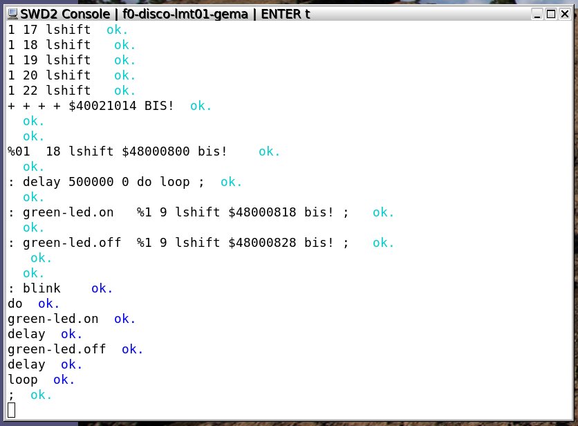
When you enter blink the GREEN led should blink until the board is reset ? If it doesn’t, then some step above didn’t work, just revisit them until you find what it was and fix it.
Conclusion
That’s all folks, CONTACT ME if you find problems, errors etc.
