bluepill-gpio README
Project: bluepill-gpio
Created: Sat 20 Feb 2021 20:56:16 AEDT
Author 2021 by t.j.porter <terry@tjporter.com.au>
Purpose: Simplifying the STM32F103 GPIO
Intended Audience: Forth Bluepill/STM32F103 users.
MCU: STM32F103, STM32F1xxx
Board: Bluepill
Core:
Required:
Recommended:
Based on:
Literature:
bluepill-gpio URL: https://mecrisp-stellaris-folkdoc.sourceforge.io/bluepill/bluepill-gpio/readme.html#bluepill-gpio
license: MIT, please see COPYING
The STM32F1xx GPIO configuration is unique among the STM32 MCU range. This is probably because it was their first Cortex-M product when released in 2004.
The STM32F1xxx Port configuration registers are controlled by two interdependent Bitfields named “MODEx AND CNFx”. This strategy is a little confusing so STMicro added a second table, (table 20) to further explain how it works. Personally, I didn’t find it very helpful.
Configuring the Port Configuration Register correctly is quite tedious as CNFx affects the configuration in MODEx and vice versa.
STM32F1xx Port Configuration Register
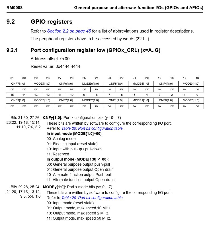
Table 20.
Port bit configuration table
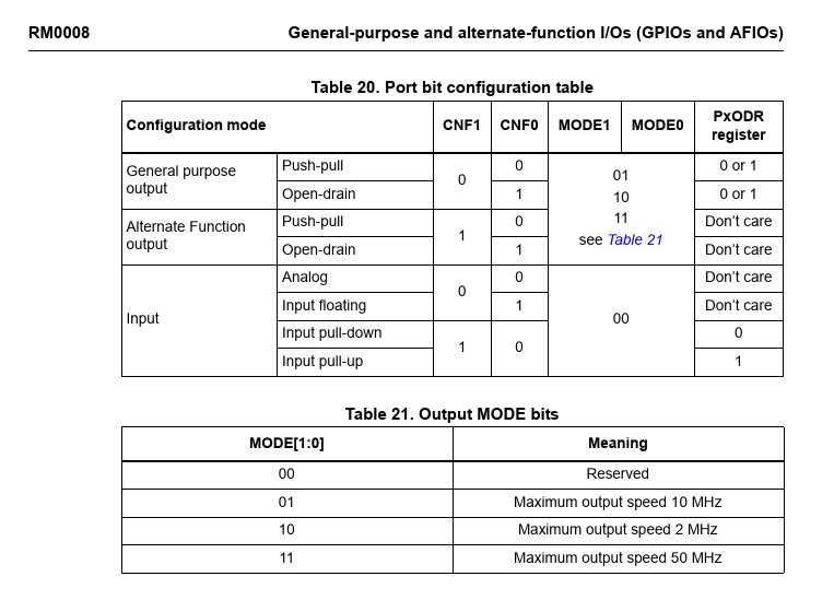
Sample code to configure GPIOA-0 as a input with a pull down resistor looks like this using the autotransformed Bitfields of https://mecrisp-stellaris-folkdoc.sourceforge.io/register-generator.html#svd2forth:
STMicro Code Example
$40010800 constant GPIOA ( General purpose I/O )
GPIOA $0 + constant GPIOA_CRL ( read-write )
: GPIOA_CRL_MODE0 ( %bb -- x addr ) GPIOA_CRL ;
: GPIOA_CRL_CNF0 ( %bb -- x addr ) 2 lshift GPIOA_CRL ;

%11 GPIOA_CRL_CNF0 BIC!      \ at reset all CNFx are set to %10 (input. floating) so these need to be cleared
%10 GPIOA_CRL_CNF0 BIS!      \ Input, pullup/down, ODR-0 is 0 (default) so it has a pull down already
This is a simple example, it is suggested as an exercise that the reader configure PA-0 as a open drain output and test it on a Bluepill to confirm it works as expected.
A Simpler Way
What if the “STM32F1xx Port Configuration Register” above was rewritten such that the MODE and CONF Bitfields were combined into one Bitfield named “MODER” ?
MODER
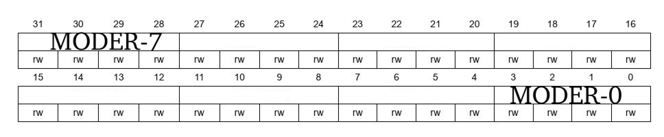
MODER Bitfields
This Truth Table lists all the MODER-x bit variations.
MODER-x |
Function |
|---|---|
0000 |
input, analog |
0001 |
output, push-pull, 10 mhz |
0010 |
output, push-pull, 2 mhz |
0011 |
output, push-pull, 50 mhz |
0100 |
input, floating |
0101 |
output, open-drain, 10 mhz |
0110 |
output, open-drain, 2 mhz |
0111 |
output, open-drain, 50 mhz |
1000 |
input, pullx |
1001 |
output, alt func, push-pull, 10 mhz |
1010 |
output, alt func, push-pull, 2 mhz |
1011 |
output, alt func, push-pull, 50 mhz |
1100 |
reserved |
1101 |
output, alt func, open-drain, 10 mhz |
1110 |
output, alt func, open-drain, 2 mhz |
1111 |
output, alt func, open-drain, 50 mhz |
We can see from this table that there are really only seven choices if we consider mhz as a sub option.
Simplified MODER Bitfields
Here I choose to use the 10 mhz risetime option for all outputs because it varies with Vcc and GPIO load anyway. This option is not even present on the later Cortex-M0 series.
MODER-x |
Function |
|---|---|
0000 |
input, analog |
0001 |
output, push-pull, 10 mhz |
0100 |
input, floating |
0101 |
output, open-drain, 10 mhz |
1000 |
pulldown ODR = 0 pullup ODR = 1 |
1001 |
output, alt func, push-pull, 10 mhz |
1101 |
output, alt func, open-drain, 10 mhz |
Converting these values into Forth CONSTANTS with sensible names:
GPIO Constants
%0000 constant input.analog     \ input, analog
%0001 constant output.pp        \ output, push-pull, 10 mhz
%0100 constant input.floating   \ input, floating
%0101 constant output.od        \ output, open-drain, 10 mhz
%1000 constant input.pullx      \ pulldown ODR = 0 pullup ODR = 1
%1001 constant output.af.pp     \ output, alt func, push-pull, 10 mhz
%1101 constant output.af.od     \ output, alt func, open-drain, 10 mhz
As per the example above an auto-transformed Word from the SVD is used for GPPIOA-0 along with the constant table to configure GPIOA-0 as input with a pull down resistor.
MODER Code Example
%0000 constant input.analog     \ input, analog
%0001 constant output.pp        \ output, push-pull, 10 mhz
%0100 constant input.floating   \ input, floating
%0101 constant output.od        \ output, open-drain, 10 mhz
%1000 constant input.pullx      \ pulldown ODR = 0 pullup ODR = 1
%1001 constant output.af.pp     \ output, alt func, push-pull, 10 mhz
%1101 constant output.af.od     \ output, alt func, open-drain, 10 mhz

$40010800 constant GPIOA ( General purpose I/O )
GPIOA $0 + constant GPIOA_CRL ( read-write )
: GPIOA_MODER0 ( %bbbb -- x addr ) GPIOA_CRL ; \ GPIOA

$F GPIOA_MODER0 BIC!            \ clear all 4 MODER bits first
input.pullx GPIOA_MODER0 BIS!   \ Input, pullup/down, ODR-0 is 0 (default) so it has a pull down already
This is a simple example, it is suggested as an exercise that the reader configure PA-0 as a open drain output using this method and test it on a Bluepill.
How does this compare to the standard STMicro method ? Is it more readable and less confusing ?
