> What’s New ? <
C V/S Forth Comparison 2
It’s now October 2023 and I’ve been learning Forth since 2014 when I switched from the C Programming Language (for embedded) back then.
I swear that C seems more and more alien to me now, I can barely read it anymore because it’s full of “Magic Numbers” which require the STM32F407 Reference Manual to decode.
Here the coder obviously had to refer to the Reference Manual to write this code, then hand enter the config based of what he read and his understanding of it.
C Code Breakdown
Here the comment states “//Set SCL pin mode as alternate function” with the actual AF being set later.
PB6 Moder is 2 bits wide (the BitWidth) starting at bit 12 (the BitOffset)
GPIOB->MODER &= ~(1U<<12);
is clearing the bit in the 12th position of the GPIOB mode register while leaving all other bits unchanged.
GPIOB->MODER |= 1U<<13;
is setting the 13th bit of the GPIO MODER register of GPIO port B to 1, while leaving all other bits unchanged.
So PB6 Moder is being set to “0x10” which is AF Mode. Because Bit 12 could have been HIGH previously, it is cleared here.
//Set SCL pin mode as alternate function
GPIOB->MODER &= ~(1U<<12);
GPIOB->MODER |= 1U<<13;
Compare this to similar Forth Source in my code below ?
PA1 Moder is being set to ANALOG mode which is 0x11 so both bits 1 and 2 are being set via BIS!. Clearing is not required.
ANALOG GPIOA_MODER_MODER1<< GPIOA_MODER bis!
Plang2 uploads this code as
%11 2 lshift $48000000 bis!
What do you think, is one easier to understand than the other ?
C Source
#include "stm32f407xx.h"
</*PB6 ----> SCL
  *PB7 ----> SDA */

void i2c1_init(void){
       //Enable GPIO clock
       RCC->AHB1ENR |= RCC_AHB1ENR_GPIOBEN;
       //Set SCL pin mode as alternate function
       GPIOB->MODER &= ~(1U<<12);
       GPIOB->MODER |= 1U<<13;
       //Set SDA pin mode as alternate function
       GPIOB->MODER &= ~(1U<<14);
       GPIOB->MODER |= 1U<<15;
       //Select alternate function for SCL pin
       GPIOB->AFR[0] &=~(1U<<24);
       GPIOB->AFR[0] &=~(1U<<25);
       GPIOB->AFR[0] |=(1U<<26);
       GPIOB->AFR[0] &=~(1U<<27);
       //Select alternate function for SDA pin
       GPIOB->AFR[0] &=~(1U<<28);
       GPIOB->AFR[0] &=~(1U<<29);
       GPIOB->AFR[0] |=(1U<<30);
       GPIOB->AFR[0] &=~(1U<<31);
       //Configure the SCL pin output type
       GPIOB->OTYPER |=(1U<<6);
       GPIOB->OTYPER |=(1U<<7);
       //Configure the SDA pin output type
       //Configure the SCL pin pull-up register
       GPIOB->PUPDR |=(1U<<12);
       GPIOB->PUPDR &=~(1U<<13);
       GPIOB->PUPDR |=(1U<<14);
       GPIOB->PUPDR &=~(1U<<15);
       //Configure the SDA pin pull-up register
       //Enable the clock access to I2C1
       RCC->APB1ENR |= RCC_APB1ENR_I2C1EN;
       //Software reset enable
       I2C1->CR1 |= I2C_CR1_SWRST;
       //Software reset disable
       I2C1->CR1 &= ~I2C_CR1_SWRST;
       //Configure I2C_CR2 peripheral clock frequency [16MHz]
       I2C1->CR2 = (1U<<4);
       //Configure I2C_CCR register standard frequency
       I2C1->CCR = 80;
       //Configure I2C_TRISE
       I2C1->TRISE = 17;
       //Enable I2C Control Register
       I2C1->CR1 |= I2C_CR1_PE;
}
Forth Plang2 Source
Now my Forth source, note the total lack of “Magic Numbers” ?
Sure it’s Forth, and you have to know Forth to read it, but all the Bitfields are CMSIS-SVD compliant (with the exception of the “>” or “<<” suffixes) and the syntax is provided by a Plang2 database search as I wrote the code.
: gpio-init ( -- )
RCC_AHBENR_IOPAEN>     \ enable GPIOA for inputs
RCC_AHBENR_IOPCEN>     \ enable GPIOC for leds
+ RCC_AHBENR bis!

\ PA1 is COMP1 & 2 INPUT. I/Os used as comparators inputs must be configured in analog mode.
ANALOG GPIOA_MODER_MODER1<< GPIOA_MODER bis!

\ PA5 is TIM2_CH1_ETR external clock via AF2
AF GPIOA_MODER_MODER5<< GPIOA_MODER bis!
AF2 GPIOA_AFRL_AFRL5<< GPIOA_AFRL bis!

\ PA6 COMP1 OUT for LMT01 pulses
AF  GPIOA_MODER_MODER6<< GPIOA_MODER bis!
AF7 GPIOA_AFRL_AFRL6<<  GPIOA_AFRL bis!

\ PA7 is INPUT for TIM14_CH1 via AF4
AF GPIOA_MODER_MODER7<< GPIOA_MODER bis!
AF4 GPIOA_AFRL_AFRL7<<  GPIOA_AFRL bis!

\ PA12 is COMP2 out via AF7 for LED
AF GPIOA_MODER_MODER12<< GPIOA_MODER bis!         \ select AF mode
AF7 GPIOA_AFRH_AFRH12<< GPIOA_AFRH bis!           \ set AF7 for PA12

\ Power to LMT-01 via PC1
OUTPUT GPIOC_MODER_MODER1<<  GPIOC_MODER BIS!     \ PC1 to output (%01) PUSH PULL
GPIOC_BSRR_BR1>  GPIOC_BSRR !                     \ PC1 set

\ GPIOC 8 and 9 drive leds
OUTPUT GPIOC_MODER_MODER8<<                       \ blue led
OUTPUT GPIOC_MODER_MODER9<<                       \ green led
+ GPIOC_MODER BIS!
;
Plang2 Database search
Note
Plang2 DB will be integrated into VIM soon.
# ./plang -p RCC -b RCC_AHBENR_IO -S
name                       stack       operation                       ar  bw  bo  description
-------------------------  ----------  ------------------------------  --  --  --  ----------------------------------------
RCC_AHBENR_IOPAEN>         ( -- x )    1 17 lshift                     rw  1   17  I/O port A clock enable
RCC_AHBENR_IOPBEN>         ( -- x )    1 18 lshift                     rw  1   18  I/O port B clock enable
RCC_AHBENR_IOPCEN>         ( -- x )    1 19 lshift                     rw  1   19  I/O port C clock enable
RCC_AHBENR_IOPDEN>         ( -- x )    1 20 lshift                     rw  1   20  I/O port D clock enable
RCC_AHBENR_IOPFEN>         ( -- x )    1 22 lshift                     rw  1   22  I/O port F clock enable

# ./plang -p GPIOA  -b GPIOA_MODER_MODER -S
name                       stack       operation                       ar  bw  bo  description
-------------------------  ----------  ------------------------------  --  --  --  ----------------------------------------
GPIOA_MODER_MODER15<<      ( x -- x )  30 lshift                       rw  2   30  Port x configuration bits (y = 0..15)
GPIOA_MODER_MODER14<<      ( x -- x )  28 lshift                       rw  2   28  Port x configuration bits (y = 0..15)
GPIOA_MODER_MODER13<<      ( x -- x )  26 lshift                       rw  2   26  Port x configuration bits (y = 0..15)
GPIOA_MODER_MODER12<<      ( x -- x )  24 lshift                       rw  2   24  Port x configuration bits (y = 0..15)
GPIOA_MODER_MODER11<<      ( x -- x )  22 lshift                       rw  2   22  Port x configuration bits (y = 0..15)
GPIOA_MODER_MODER10<<      ( x -- x )  20 lshift                       rw  2   20  Port x configuration bits (y = 0..15)
GPIOA_MODER_MODER9<<       ( x -- x )  18 lshift                       rw  2   18  Port x configuration bits (y = 0..15)
GPIOA_MODER_MODER8<<       ( x -- x )  16 lshift                       rw  2   16  Port x configuration bits (y = 0..15)
GPIOA_MODER_MODER7<<       ( x -- x )  14 lshift                       rw  2   14  Port x configuration bits (y = 0..15)
GPIOA_MODER_MODER6<<       ( x -- x )  12 lshift                       rw  2   12  Port x configuration bits (y = 0..15)
GPIOA_MODER_MODER5<<       ( x -- x )  10 lshift                       rw  2   10  Port x configuration bits (y = 0..15)
GPIOA_MODER_MODER4<<       ( x -- x )  8 lshift                        rw  2   8   Port x configuration bits (y = 0..15)
GPIOA_MODER_MODER3<<       ( x -- x )  6 lshift                        rw  2   6   Port x configuration bits (y = 0..15)
GPIOA_MODER_MODER2<<       ( x -- x )  4 lshift                        rw  2   4   Port x configuration bits (y = 0..15)
GPIOA_MODER_MODER1<<       ( x -- x )  2 lshift                        rw  2   2   Port x configuration bits (y = 0..15)
GPIOA_MODER_MODER0<<       ( x -- x )  0 lshift                        rw  2   0   Port x configuration bits (y = 0..15)

# ./plang -p GPIOA  -b  GPIOA_AFRL_AFRL -S
Bitfield print (-B)
name                       stack       operation                       ar  bw  bo  description
-------------------------  ----------  ------------------------------  --  --  --  ----------------------------------------
GPIOA_AFRL_AFRL7<<         ( x -- x )  28 lshift                       rw  4   28  Alternate function selection for port x
GPIOA_AFRL_AFRL6<<         ( x -- x )  24 lshift                       rw  4   24  Alternate function selection for port x
GPIOA_AFRL_AFRL5<<         ( x -- x )  20 lshift                       rw  4   20  Alternate function selection for port x
GPIOA_AFRL_AFRL4<<         ( x -- x )  16 lshift                       rw  4   16  Alternate function selection for port x
GPIOA_AFRL_AFRL3<<         ( x -- x )  12 lshift                       rw  4   12  Alternate function selection for port x
GPIOA_AFRL_AFRL2<<         ( x -- x )  8 lshift                        rw  4   8   Alternate function selection for port x
GPIOA_AFRL_AFRL1<<         ( x -- x )  4 lshift                        rw  4   4   Alternate function selection for port x
GPIOA_AFRL_AFRL0<<         ( x -- x )  0 lshift                        rw  4   0   Alternate function selection for port x
Mecrisp-Stellaris-VIM-Syntax-Highlighter is a forth language plugin for VIM to make coding forth projects faster and easier.
The plugin provides help files for standard Mecrisp-Stellaris words as well as MCU specific peripheral-register-bitfield words.
It also tracks your current project as you create new code and save forth files. It creates syntax highlighting for your project words as well as tag links you can follow to see where your words were defined.
If you need help remembering a word while coding, the plugin provides word-completion lists on demand.
Summary
There is a lot more of the C source code at https://www.eevblog.com/forum/microcontrollers/stm32f407vg-i2c-mems-sensor-value-reading-bare-metal-programming/ and personally I think the author has done a great job. He has checked his code four times and it’s well written for embedded C in my opinion. He has kept it low level so at least I can slowly work thru his code in order to understand it.
That said, his project still doesn’t work as of 23 Oct 2023 where he said “I have a discovery board with stm32f407vg-t6.There is a mems sensor on it and I am trying to read sensor values via I2C. However, my code is not working.”
Why is it not working ?
I don’t have a clue and although the author has received a few suggestions, they have not helped.
I’m not very surprised because embedded C is complex compared to embedded Forth where the Forth “interactivity” allows the programmer to test every Word (subroutine) which means the project is fully tested as it is developed.
C on the other hand has no interactivity, so programmers have to build the whole project and then debug it all, usually deploying GDB, which isn’t easy to use and is no help so far as the author reports.
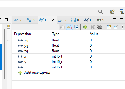
Authors comment: “Edit: I can’t see sometimes even 0 values in the debug mode.”