F0 Disco Lmt01 Gema
The creation of a new Forth Development system requires testing to uncover bugs, so once SVD2FORTH-V6 reached a useful stage f0-disco-lmt01-gema was created.
The Test
One can’t test a Forth development system on an embedded MCU by creating a software program alone. Embedded Forth testing requires that MCU peripherals be used, and to that end this test uses a LMT-01 thermometer chip, the TIM2 timer and Comparators 1 and 2 on a SMT32F051 MCU F0 DISCOVERY BOARD.
Reading The Temperature
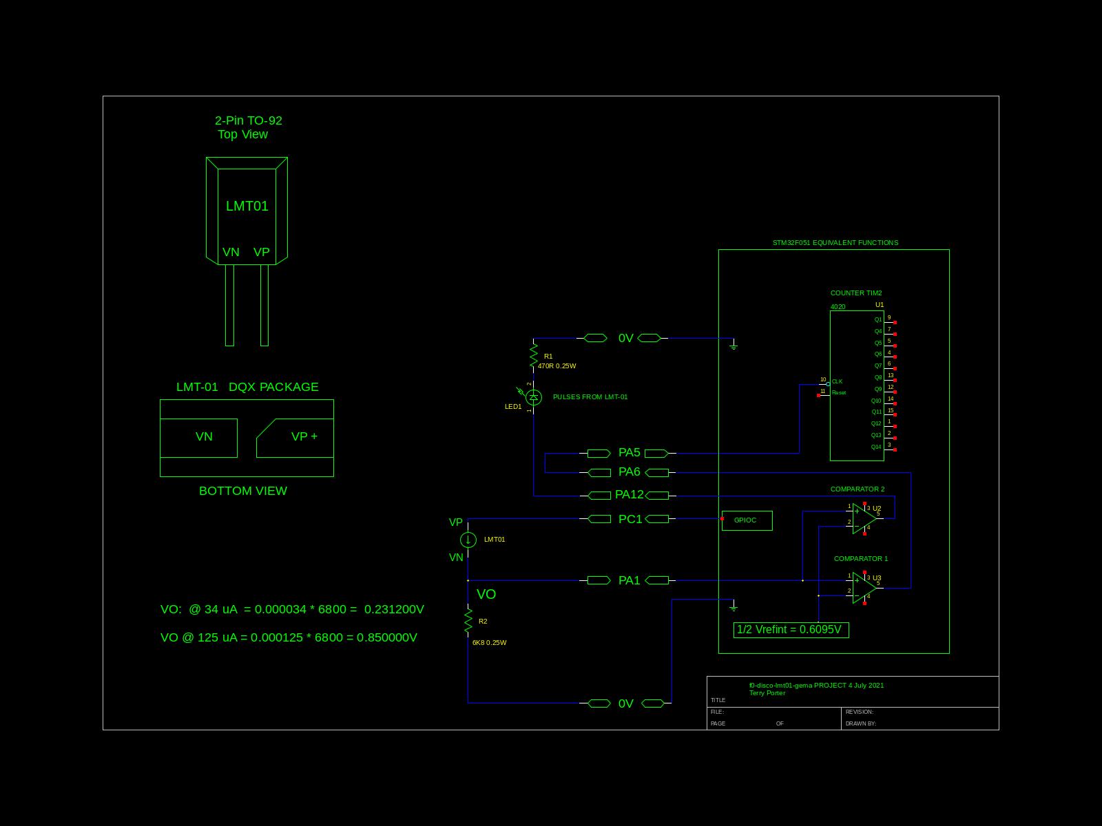
The schematic below shows the STM32F0 Discovery board connections used, and a ‘equivalent functions’ diagram of the MCU peripherals. PC1 supplies power to the LMT-01 sensor when a temperature reading is needed, this takes a maximum of 100mS. PA1 feeds the voltage developed by the current pulses to comparators one and two.
Comparator-2 drives a Indicator LED so the user can see that the sensor is indeed sending data. Comparator-1 sends the same data to TIM2 which counts them. The comparators compare the voltage from R2 against a MCU internal voltage reference of 0.6095 volts which represents a logic High. Hysteresis is configured for ‘medium’.
The software then produces a temperature printout in degrees C and F to one decimal place based on the total pulse count.
Finer detail should be easily obtained by reading the source, if it’s not, please let me know.
Svd2forth-v6
This project consists of six source files which are concatenated, run thru the preprocessor (to generate the includes.fs file), stripped of comments and blank lines then uploaded to the on-chip Forth.
Files are uploaded in sequence, lowest number first .
No |
File |
Description |
|---|---|---|
1 |
sys.fs |
My general system files, 48MHz clock, 1mS delay, hardware exception tracer |
2 |
includes.fs |
Auto generated source dependencies |
3 |
gpio.fs |
Configure the GPIO’s |
4 |
comparator.fs |
Set up the comparator so it receives the LMT-01 pulses |
5 |
pulse.fs |
Configure TIM2 to count the comparator pulses |
6 |
f0-disco-lmt01-gema.fs |
Tie all the above files together |
A Word about Bitfields
This is a important part of svd2forth-v6 so I have made a separate page for it. Please read it before proceeding if you haven’t already.
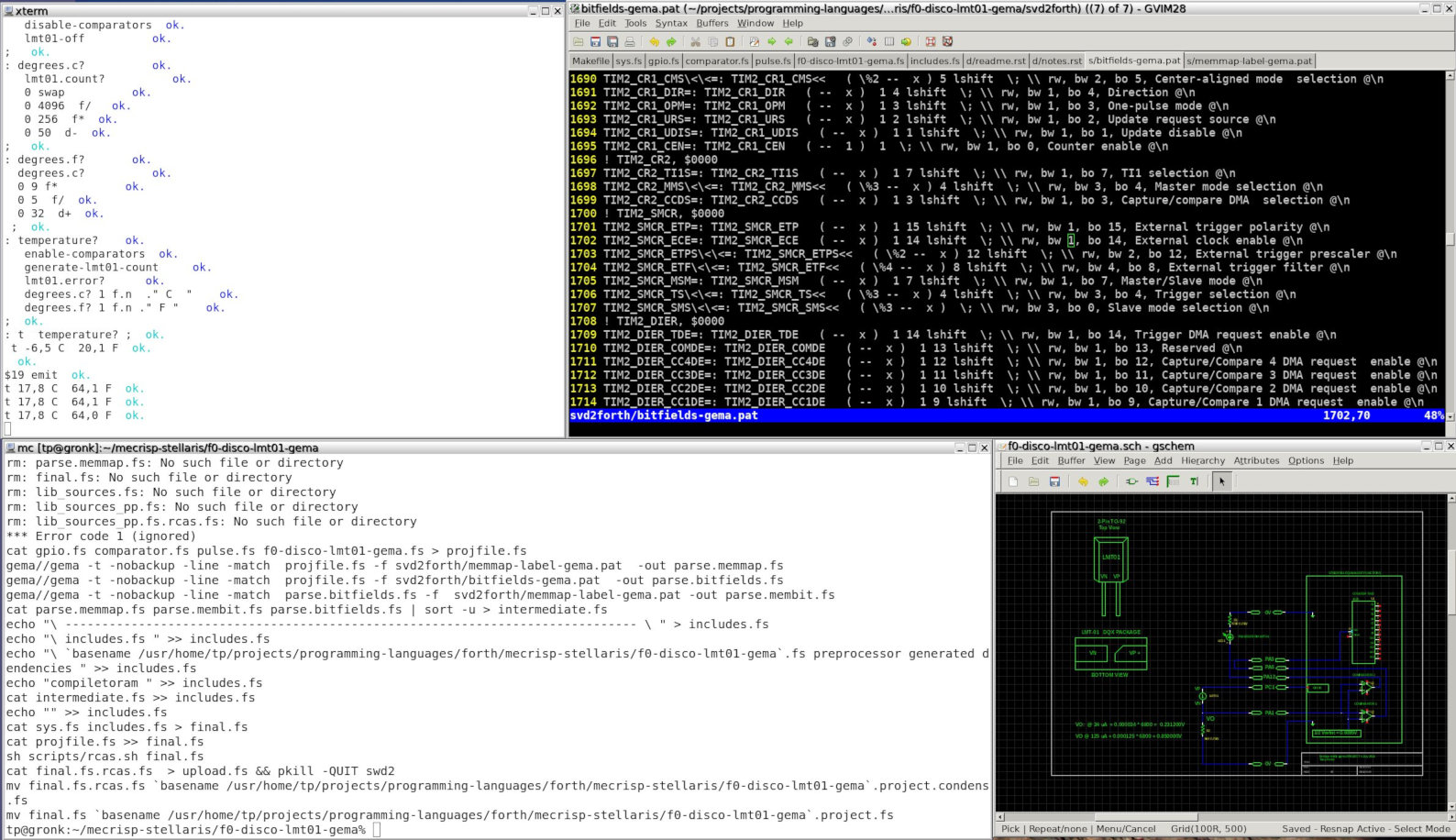
Now including a preview screenshot of my prototype Bitfield Viewer and select tool.
The Source Code
\ ------------------------------------------------------------------------------ \
\ sys.fs
\ purpose: set up system utilities
\ Not preprocessed.

compiletoram

   init.calltrace	   \ Prevent "Unhandled Interrupt ..." and list the problem instead.
   48mhz		   \ Increase MCU clock to 48 MHz
   48000 init.systick	   \ Set the Systick to 1ms increments

\ ------------------------------------------------------------------------------ \
\ includes.fs
\ f0-disco-lmt01-gema.fs preprocessor generated dependencies
compiletoram
$40000000 constant TIM2_CR1 \ control register 1
$40000008 constant TIM2_SMCR \ slave mode control register
$40000024 constant TIM2_CNT \ counter
$4001001C constant COMP_CSR \ control and status register
$40021014 constant RCC_AHBENR \ AHB Peripheral Clock enable register  RCC_AHBENR
$40021018 constant RCC_APB2ENR \ APB2 peripheral clock enable register  RCC_APB2ENR
$4002101C constant RCC_APB1ENR \ APB1 peripheral clock enable register  RCC_APB1ENR
$48000000 constant GPIOA_MODER \ GPIO port mode register
$48000020 constant GPIOA_AFRL \ GPIO alternate function low  register
$48000024 constant GPIOA_AFRH \ GPIO alternate function high  register
$48000800 constant GPIOC_MODER \ GPIO port mode register
$48000818 constant GPIOC_BSRR \ GPIO port bit set/reset  register
: COMP_CSR_COMP1EN   ( --  1 )  1  ; \ rw, bw 1, bo 0, Comparator 1 enable
: COMP_CSR_COMP1HYST<<   ( %2 --  x ) 12 lshift  ; \ rw, bw 2, bo 12, Comparator 1 hysteresis
: COMP_CSR_COMP1INSEL<<   ( %3 --  x ) 4 lshift  ; \ rw, bw 3, bo 4, Comparator 1 inverting input  selection
: COMP_CSR_COMP1MODE<<   ( %2 --  x ) 2 lshift  ; \ rw, bw 2, bo 2, Comparator 1 mode
: COMP_CSR_COMP1OUTSEL<<   ( %3 --  x ) 8 lshift  ; \ rw, bw 3, bo 8, Comparator 1 output  selection
: COMP_CSR_COMP2EN   ( --  x )  1 16 lshift  ; \ rw, bw 1, bo 16, Comparator 2 enable
: COMP_CSR_COMP2HYST<<   ( %2 --  x ) 28 lshift  ; \ rw, bw 2, bo 28, Comparator 2 hysteresis
: COMP_CSR_COMP2INSEL<<   ( %3 --  x ) 20 lshift  ; \ rw, bw 3, bo 20, Comparator 2 inverting input  selection
: COMP_CSR_COMP2MODE<<   ( %2 --  x ) 18 lshift  ; \ rw, bw 2, bo 18, Comparator 2 mode
: COMP_CSR_COMP2OUTSEL<<   ( %3 --  x ) 24 lshift  ; \ rw, bw 3, bo 24, Comparator 2 output  selection
: COMP_CSR_WNDWEN   ( --  x )  1 23 lshift  ; \ rw, bw 1, bo 23, Window mode enable
: GPIOA_AFRH_AFRH12<<   ( %4 --  x ) 16 lshift  ; \ rw, bw 4, bo 16, Alternate function selection for port x  bit y y = 8..15
: GPIOA_AFRL_AFRL5<<   ( %4 --  x ) 20 lshift  ; \ rw, bw 4, bo 20, Alternate function selection for port x  bit y y = 0..7
: GPIOA_AFRL_AFRL6<<   ( %4 --  x ) 24 lshift  ; \ rw, bw 4, bo 24, Alternate function selection for port x  bit y y = 0..7
: GPIOA_AFRL_AFRL7<<   ( %4 --  x ) 28 lshift  ; \ rw, bw 4, bo 28, Alternate function selection for port x  bit y y = 0..7
: GPIOA_MODER_MODER12<<   ( %2 --  x ) 24 lshift  ; \ rw, bw 2, bo 24, Port x configuration bits y =  0..15
: GPIOA_MODER_MODER1<<   ( %2 --  x ) 2 lshift  ; \ rw, bw 2, bo 2, Port x configuration bits y =  0..15
: GPIOA_MODER_MODER5<<   ( %2 --  x ) 10 lshift  ; \ rw, bw 2, bo 10, Port x configuration bits y =  0..15
: GPIOA_MODER_MODER6<<   ( %2 --  x ) 12 lshift  ; \ rw, bw 2, bo 12, Port x configuration bits y =  0..15
: GPIOA_MODER_MODER7<<   ( %2 --  x ) 14 lshift  ; \ rw, bw 2, bo 14, Port x configuration bits y =  0..15
: GPIOC_BSRR_BR1!    ( --  ) 1 17 lshift GPIOC_BSRR !  ; \ wo, bw 1, bo 17, Port x reset bit y y =  0..15
: GPIOC_BSRR_BS1!    ( --  ) 1 1 lshift GPIOC_BSRR !  ; \ wo, bw 1, bo 1, Port x set bit y y=  0..15
: GPIOC_MODER_MODER1<<   ( %2 --  x ) 2 lshift  ; \ rw, bw 2, bo 2, Port x configuration bits y =  0..15
: RCC_AHBENR_IOPAEN   ( --  x )  1 17 lshift  ; \ rw, bw 1, bo 17, I/O port A clock enable
: RCC_AHBENR_IOPCEN   ( --  x )  1 19 lshift  ; \ rw, bw 1, bo 19, I/O port C clock enable
: RCC_APB1ENR_TIM2EN   ( --  1 )  1  ; \ rw, bw 1, bo 0, Timer 2 clock enable
: RCC_APB2ENR_SYSCFGEN   ( --  1 )  1  ; \ rw, bw 1, bo 0, SYSCFG clock enable
: TIM2_CR1_CEN   ( --  1 )  1  ; \ rw, bw 1, bo 0, Counter enable
: TIM2_SMCR_ETF<<   ( %4 --  x ) 8 lshift  ; \ rw, bw 4, bo 8, External trigger filter
: TIM2_SMCR_SMS<<   ( %3 --  x )  ; \ rw, bw 3, bo 0, Slave mode selection
: TIM2_SMCR_TS<<   ( %3 --  x ) 4 lshift  ; \ rw, bw 3, bo 4, Trigger selection

\ ------------------------------------------------------------------------------ \
\ gpio.fs
\ purpose: gpio configs
\ PA1 is ANALOG INPUT for LMT-01 PULSES
\ PC1 is OUTPUT HIGH to power LMT-01 or FLOATING to disable LMT-01

: gpio-init ( -- )
\ Enable GPIOA and GPIOC
RCC_AHBENR_IOPAEN
RCC_AHBENR_IOPCEN
+ RCC_AHBENR bis!

\ PA1 is COMP1 & 2 INPUT. I/Os used as comparators inputs must be configured in analog mode.
ANALOG GPIOA_MODER_MODER1<< GPIOA_MODER bis!

\ PA5 is TIM2_CH1_ETR external clock via AF2
AF GPIOA_MODER_MODER5<< GPIOA_MODER bis!
AF2 GPIOA_AFRL_AFRL5<< GPIOA_AFRL bis!

\ PA6 COMP1 OUT for LMT01 pulses
AF  GPIOA_MODER_MODER6<< GPIOA_MODER bis!
AF7 GPIOA_AFRL_AFRL6<<  GPIOA_AFRL bis!

\ PA7 is INPUT for TIM14_CH1 via AF4
AF GPIOA_MODER_MODER7<< GPIOA_MODER bis!
AF4 GPIOA_AFRL_AFRL7<<  GPIOA_AFRL bis!

\ PA12 is COMP2 out via AF7 for LED
 AF GPIOA_MODER_MODER12<< GPIOA_MODER bis!	   \ select AF mode
 AF7 GPIOA_AFRH_AFRH12<< GPIOA_AFRH bis!	   \ set AF7 for PA12

\ Power to LMT-01 via PC1
OUTPUT GPIOC_MODER_MODER1<<  GPIOC_MODER BIS!	   \ PC1 to output (%01) PUSH PULL
GPIOC_BSRR_BR1!					   \ PC1 set LOW
;

: lmt01-on ( -- )
   GPIOC_BSRR_BS1!				   \ PC1 set HIGH, this powers the LMT-01, pulses start in 50 mS
;

: lmt01-off ( -- )
  GPIOC_BSRR_BR1!
;

\ ------------------------------------------------------------------------------ \
\ comparator.fs
\ purpose: detect high and low logic levels from the LMT-01
\ Design:
\ GPIOA-1 is ANALOG INPUT for LMT-01 PULSES
\ GPIOC-1 is OUTPUT HIGH to power LMT-01 or FLOATING to disable LMT-01
\ Comp ref input =  1/2 Vrefint = 0.6095
\ notes:
\ The comparator outputs can be redirected to an I/O or to timer inputs for triggering:

: comp-init ( -- )
\ Enable COMPARATOR CLOCK, this is done in tandem with SYSCFGEN
RCC_APB2ENR_SYSCFGEN RCC_APB2ENR bis!

\ Configure Comp 1
%11 COMP_CSR_COMP1MODE<<      \ COMP1 INPUT MODE: %00 High speed / full power 10: Low speed / low-power
%001 COMP_CSR_COMP1INSEL<<    \ COMP1 INPUT SELECT: %001 1/2 of VREFINT = 0.6095V
%100 COMP_CSR_COMP1OUTSEL<<   \ COMP1 OUTPUT SELECT: %100: Timer 2 input capture 4
%10 COMP_CSR_COMP1HYST<<      \ COMP1 HYSTERESIS: %10 Medium hysteresis
+ + + COMP_CSR bis!

\ Configure Comp2 to drive Disco LED when LMT-01 pulses for user visual feedback
\ Connect a LED (with resistor) to PA12 and ground. AF will select PA12
%11 COMP_CSR_COMP2MODE<<      \ COMP2 INPUT MODE: %00 High speed / full power 11: Very-low speed / ultra-low power
%001 COMP_CSR_COMP2INSEL<<    \ COMP2 INPUT SELECT: %001 1/2 of VREFINT = 0.6095V
%110 COMP_CSR_COMP2OUTSEL<<   \ COMP2 OUTPUT SELECT: %110: Timer 3 input capture 1
%10 COMP_CSR_COMP2HYST<<      \ COMP2 HYSTERESIS: %10 Medium hysteresis
COMP_CSR_WNDWEN		      \ Window mode: connects the non-inverting input of COMP2 to COMP1's n-i input
+ + + + COMP_CSR bis!
;

: enable-comparators ( -- )
   COMP_CSR_COMP1EN  	      \ Enable COMP1
   COMP_CSR_COMP2EN	      \ Enable COMP2
   + COMP_CSR bis!
;

: disable-comparators ( -- )
   COMP_CSR_COMP1EN	      \ Enable COMP1
   COMP_CSR_COMP2EN	      \ Enable COMP2
   + COMP_CSR bic!
;

\ ------------------------------------------------------------------------------ \
\ pulse.fs
\ purpose: count pulses from the LMT-01 temperature sensor using TIM2
\ Comp1 output --> PA6, LMT01 pulses
\ Comp2 output --> PA12, plus (not implimented yet) timeout for final LMT01 pulse
\ PA5 is TIM2_CH1_ETR external clock via AF2

: counters-init ( -- )
\ Timer 2 enable CLOCKS
 RCC_APB1ENR_TIM2EN RCC_APB1ENR  bis!

\ Timer 2 config for pulse counting
%111 TIM2_SMCR_SMS<<	\ %111: External Clock Mode 1 - Rising edges of the selected trigger (TRGI) clock the counter.
%111 TIM2_SMCR_TS<<	\ %111: External Trigger input (ETRF)
%0001 TIM2_SMCR_ETF<<	\ %0011: fSAMPLING = fCK_INT, N = 8
+ + TIM2_SMCR bis!

TIM2_CR1_CEN TIM2_CR1 bis! \ enable timer2
;
\ ---------------------------------------------------------------------------\
\ Program Name: f0-disco-lmt01-gema.fs
\ Date: Tue 18 Jun 2021 16:51:24 AEST
\ Copyright 2021 by t.j.porter <terry@tjporter.com.au>,  MIT Licensed
\ For Mecrisp-Stellaris by Matthias Koch. \ https://sourceforge.net/projects/mecrisp/
\ Chip: STM32F051
\ Board: STM32F0 Discovery Board
\ All register names are CMSIS-SVD compliant
\ Short Program Description: Demo of SVD2FORTH V6 with gema using a LMT-01 thermometer
\ See doc/README.html for full description
\ User LD3: Green user LED connected to PC-9
\ User LD4: Blue user LED connected to PC-8
\ PA1 is ANALOG INPUT for LMT-01 PULSES
\ PC1 is OUTPUT HIGH to power LMT-01 or INPUT to disable LMT-01

gpio-init
comp-init
counters-init


: clear-lmt01-counter ( -- )
   $0000000 TIM2_CNT !
;

: lmt01.count? ( -- x )
  TIM2_CNT @
;

: lmt01.error?
   lmt01.count? 0 > if ( all ok )
   else ." error lm-01 fault, halting " cr quit then
;


: generate-lmt01-count ( -- ) \ LMT-01 Count is hardwired to TIM2 externally
   clear-lmt01-counter
   lmt01-on
   1 ms.delay		      \ Avoid counting lmt01 startup spike (5uS long)
   enable-comparators	      \ Receive lmt01 pulses into TIM2
   99 ms.delay		      \ Everything is done in 100mS
   disable-comparators
   lmt01-off		      \ All done
;

: degrees.c? ( -- C )	      \ convert lmt01.count to degC, Temp (C) = ((count/4096) *256) -50
   lmt01.count?		      \ fetch total number of pulses counted
   0 swap		      \ convert numbers to s31.32 and calculate
   0 4096  f/
   0 256  f*
   0 50  d-
;

: degrees.f? ( -- F * 10 )    \ Formula = (C × 9/5) + 32
  degrees.c?		      \ get LMT-01 count
  0 9 f*		      \ convert numbers to s31.32 and calculate
  0 5  f/
  0 32  d+
 ;

: temperature?  ( sensor # -- error | temperature C )
   enable-comparators
   generate-lmt01-count		 \ Get temperature
   lmt01.error?			 \ Abort if LMT-01 isn't sending pulses
   degrees.c? 1 f.n  ." C  "	 \ Print temp in C
   degrees.f? 1 f.n ." F "	 \ Using C value, calculate F and print
;

: t ( -- ) temperature? ;

 t
Program Output
t 15,3 C  59,6 F  ok.
t 15,4 C  59,7 F  ok.
t 15,4 C  59,7 F  ok.
