Interrupts
Interrupts, when they occur execute code found in a memory location (which is reserved for that interrupt), save the state of the MCU, execute the code, then restore the MCU state. There are many other optional factors affecting interrupts, such as priority, triggers and so on.
Note
In the Cortex-M programming manual, an Exception is anything that breaks the normal program flow, and invokes a handler from the vector table. Interrupts are a subset of Exceptions, coming from the peripherals outside the ARM core.
Exceptions have an Exception Number, starting from 0.
Interrupts have an IRQ Number, starting from 0.
Because all Interrupts are Exceptions, they all get an Exception Number, which is 16 higher than the IRQ Number. The Exceptions that are not Interrupts (including SysTick) have Exception Numbers in the 0-15 range, smaller than the Exception Numbers of the Interrupts. Somewhat confusingly, Exceptions that are not Interrupts have IRQ Numbers too, which by extension fall into the range from -16 to -1.
Because SysTick is implemented in the Cortex-M core, it is considered an exception, but not an interrupt having a Exception Number of 15, and IRQ Number -1.
Cortex M0 Interrupt Flowchart
NVIC
NESTED VECTORED INTERRUPT CONTROLLER
NVIC main features
32 maskable interrupt channels (not including the sixteen Cortex®-M0 interrupt lines)
4 programmable priority levels (2 bits of interrupt priority are used)
Low-latency exception and interrupt handling
Power management control
Implementation of System Control Registers
The NVIC and the processor core interface are closely coupled, which enables low latency interrupt processing and efficient processing of late arriving interrupts.
All interrupts including the core exceptions are managed by the NVIC. For more information on exceptions and NVIC programming, refer to the PM0215 programming manual.
TABLE B: Interrupt and Exception Vectors
Each Interrupt Source matches a “Position” value (see explanation below) and these are used to ENABLE the ISR. How it works is shown in the example programs segments.
Note
Depending on MCU your device may not have all the peripherals listed in this table, or may have many more.
Position |
Priority |
Type of Priority |
Interrupt Source |
Description |
Address |
|---|---|---|---|---|---|
. |
. |
. |
. |
. |
0x0000 0000 |
. |
-3 |
fixed |
Reset |
Reset |
0x0000 0004 |
. |
-2 |
fixed |
NMI |
Non maskable interrupt. |
0x0000 0008 |
. |
-1 |
fixed |
HardFault |
All class of fault |
0x0000 000C |
. |
3 |
settable |
SVCall |
System service call via SWI instruction |
0x0000 002C |
. |
5 |
settable |
PendSV |
Pendable request for system service |
0x0000 0038 |
. |
6 |
settable |
SysTick |
System tick timer (SPECIAL SEE ABOVE) |
0x0000 003C |
. |
7 |
settable |
WWDG |
Window watchdog interrupt |
0x0000 0040 |
1 |
8 |
settable |
PVD_VDDIO2 |
PVD and VDDIO2 supply comparator interrupt (combined EXTI lines 16 and 31) |
0x0000 0044 |
2 |
9 |
settable |
RTC |
RTC interrupts (combined EXTI lines 17, 19 and 20) |
0x0000 0048 |
3 |
10 |
settable |
FLASH |
Flash global interrupt |
0x0000 004C |
4 |
11 |
settable |
RCC_CRS |
RCC and CRS global interrupts |
0x0000 0050 |
5 |
12 |
settable |
EXTI0_1 |
EXTI Line[1:0] interrupts |
0x0000 0054 |
6 |
13 |
settable |
EXTI2_3 |
EXTI Line[3:2] interrupts |
0x0000 0058 |
7 |
14 |
settable |
EXTI4_15 |
EXTI Line[15:4] interrupts |
0x0000 005C |
8 |
15 |
settable |
TSC |
Touch sensing interrupt |
0x0000 0060 |
9 |
16 |
settable |
DMA_CH1 |
DMA channel 1 interrupt |
0x0000 0064 |
10 |
17 |
settable |
DMA_CH2_3 |
DMA channel 2 and 3 interrupts |
0x0000 0068 |
10 |
17 |
settable |
DMA2_CH1_2 |
DMA2 channel 1 and 2 interrupts |
0x0000 0068 |
11 |
18 |
settable |
DMA_CH4_5_6_7 |
DMA channel 4, 5, 6 and 7 interrupts |
0x0000 006C |
11 |
18 |
settable |
DMA2_CH3_4_5 |
DMA2 channel 3, 4 and 5 interrupts |
0x0000 006C |
12 |
19 |
settable |
ADC_COMP |
ADC and COMP interrupts (ADC interrupt combined with EXTI lines 21 and 22) |
0x0000 0070 |
13 |
20 |
settable |
TIM1_BRK_UP_TRG_COM |
TIM1 break, update, trigger and commutation interrupt |
0x0000 0074 |
14 |
21 |
settable |
TIM1_CC |
TIM1 capture compare interrupt |
0x0000 0078 |
15 |
22 |
settable |
TIM2 |
TIM2 global interrupt |
0x0000 007C |
16 |
23 |
settable |
TIM3 |
TIM3 global interrupt |
0x0000 0080 |
17 |
24 |
settable |
TIM6_DAC |
TIM6 global interrupt and DAC underrun interrupt |
0x0000 0084 |
18 |
25 |
settable |
TIM7 |
TIM7 global interrupt |
0x0000 0088 |
19 |
26 |
settable |
TIM14 |
TIM14 global interrupt |
0x0000 008C |
20 |
27 |
settable |
TIM15 |
TIM15 global interrupt |
0x0000 0090 |
21 |
28 |
settable |
TIM16 |
TIM16 global interrupt |
0x0000 0094 |
22 |
29 |
settable |
TIM17 |
TIM17 global interrupt |
0x0000 0098 |
23 |
30 |
settable |
I2C1 |
I2C1 global interrupt (combined with EXTI line 23) |
0x0000 009C |
24 |
31 |
settable |
I2C2 |
I2C2 global interrupt |
0x0000 00A0 |
25 |
32 |
settable |
SPI1 |
SPI1 global interrupt |
0x0000 00A4 |
26 |
33 |
settable |
SPI2 |
SPI2 global interrupt |
0x0000 00A8 |
27 |
34 |
settable |
USART1 |
USART1 global interrupt (combined with EXTI line 25) |
0x0000 00AC |
28 |
35 |
settable |
USART2 |
USART2 global interrupt (combined with EXTI line 26) |
0x0000 00B0 |
29 |
36 |
settable |
USART3_4 |
USART3 and USART4 global interrupts |
0x0000 00B4 |
30 |
37 |
settable |
CEC_CAN |
CEC and CAN global interrupts (combined with EXTI line 27) |
0x0000 00B8 |
31 |
38 |
settable |
USB |
USB global interrupt (combined with EXTI line 18) |
0x0000 00BC |
Position ?
“Position” is the number supplied to the “IMPORTANT NVIC examples” below.
In this Cortex-M0 table it stops at 31, but other Cortex-M MCUs can have “Position” values numbering into the hundreds.
Nvic_iser
The NVIC_ISERx registers are dual-purpose. If you write a 1 to a specific bit it will enable the interrupt. If you read a specific bit it will tell you if the interrupt is enabled.
If a pending interrupt is enabled the NVIC activates the interrupt based on its priority. If an interrupt is not enabled asserting its interrupt signal changes the interrupt state to pending but the NVIC never activates the interrupt regardless of its priority.
If the “pending” flag gets set then the interrupt will be served as soon as you re-enable the interrupt.
Warning
NVIC numbers 0 - 31 are accessed by NVIC_ISER0_SETENA. NVIC numbers 32 - 63 are accessed by NVIC_ISER1_SETENA, and so on. This is mentioned in only ONE place in the reference,
IMPORTANT NVIC examples
In the first example, the Binary number %1000000 equates to “Position” 6 as Bit 6 is HIGH and NVIC_ISER0_SETENA is used. NVIC_ISER0_SETENA offers “Positions” from 0 - 31.
In the second example, the Binary number %100000000 equates to “Position” 40 as Bit 8 is HIGH and NVIC_ISER1_SETENA is used. “Position” 40 isn’t available on a Cortex-M, but this example is taken from a STM32F103 Cortex-M3 MCU which has NVIC “Positions” up to number 67. NVIC_ISER1_SETENA offers “Positions” from 32 - 63.
%1000000  NVIC_ISER0_SETENA     \ enable interrupt #6
%100000000 NVIC_ISER1_SETENA    \ enable interrupt #40.  40 = 32 + 8
EXTI
EXTERNAL INTERRUPT/EVENT CONTROLLER
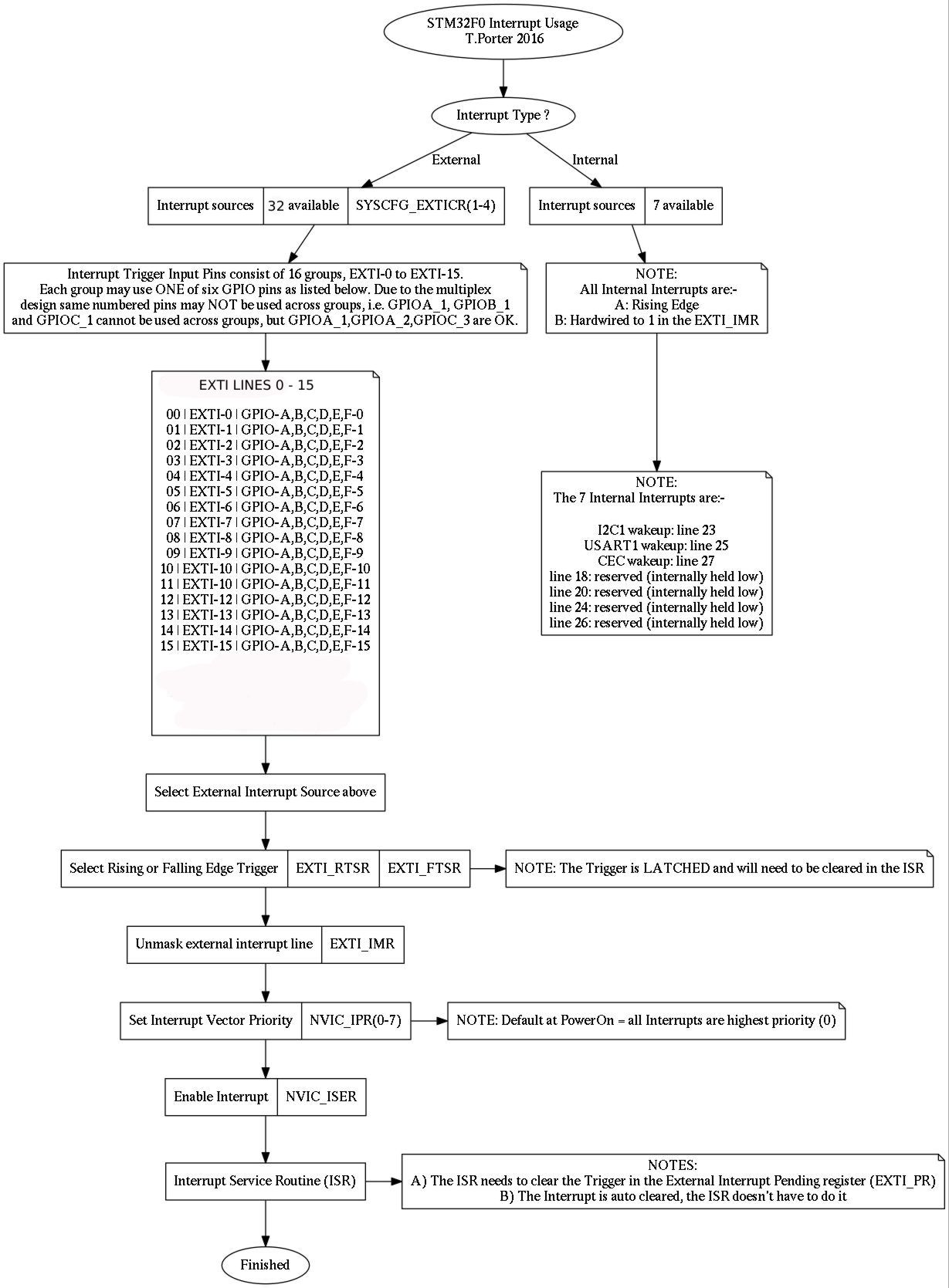
The external interrupt/event controller consists of up to 20 edge detectors in connectivity line devices, or 19 edge detectors in other devices for generating event/interrupt requests. Each input line can be independently configured to select the type (event or interrupt) and the corresponding trigger event (rising or falling or both). Each line can also masked independently. A pending register maintains the status line of the interrupt requests
EXTI controller main features
Independent trigger and mask on each interrupt/event line
Dedicated status bit for each interrupt line
Generation of up to 20 software event/interrupt requests
Detection of external signal with pulse width lower than APB2 clock period. Refer to the electrical characteristics section of the datasheet for details on this parameter.
EXTI Lines 0 - 15
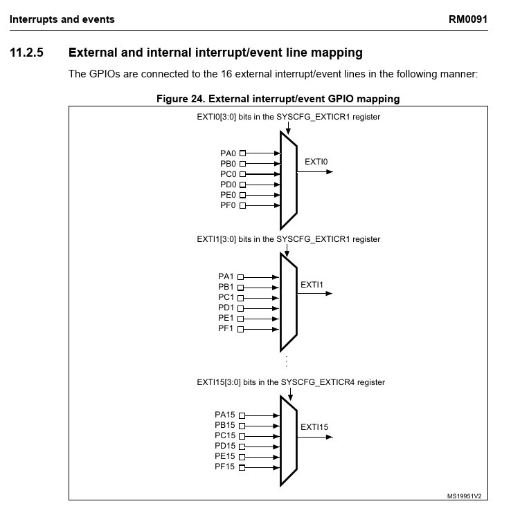
Used by the GPIO pins
TABLE A: GPIO EXTI Mapping
There are 16 ‘EXTI lines’ (EXTI0-15). Each line is driven by the same numbered bit of all GPIOs. As can be seen, six GPIOS drive the same bit numbered ‘EXTI line’ but only one GPIO can be selected per EXTI.
EXTI Lines 16 - 31
Used by the Peripherals
EXTI Line |
Connected To |
|---|---|
EXTI line 16 |
PVD output |
EXTI line 17 |
RTC Alarm event |
EXTI line 18 |
internal USB wakeup event |
EXTI line 19 |
RTC Tamper and TimeStamp events |
EXTI line 20 |
RTC Wakeup event (available only on STM32F07x and STM32F09x devices) |
EXTI line 21 |
Comparator 1 output |
EXTI line 22 |
Comparator 2 output |
EXTI line 23 |
internal I2C1 wakeup event |
EXTI line 24 |
reserved (internally held low) |
EXTI line 25 |
internal USART1 wakeup event |
EXTI line 26 |
internal USART2 wakeup event (available only on STM32F07x and STM32F09x devices) |
EXTI line 27 |
internal CEC wakeup event |
EXTI line 28 |
internal USART3 wakeup event (available only on STM32F09x devices) |
EXTI line 29 |
reserved (internally held low) |
EXTI line 30 |
reserved (internally held low) |
EXTI line 31 |
VDDIO2 supply comparator output (available only on STM32F04x, STM32F07x and STM32F09x devices |
Hardware Interrupt Selection
To configure a line as interrupt source, use the following procedure:
Choose one of the 16 GPIO EXTI mapping groups to suit your GPIO pin from TABLE A above.
Choose the GPIO for the selected EXTI.
SEL |
GPIO |
|---|---|
x000: |
PA[x] pin |
x001: |
PB[x] pin |
x010: |
PC[x] pin |
x011: |
PD[x] pin |
x100: |
PE[x] pin |
x101: |
PF[x] pin |
I.E. GPIOC-2 would be:
%X010 8 lshift $40010008 bis! \ SYSCFG_EXTICR1_EXTI2
Warning
To configure any SYSCFG registers like the one above, SYSCFGEN must be enabled in the RCC Register. If it isn’t then only GPIOA works as a trigger for EXTI !
Configure the interrupt mask bit in the EXTI_IMR register.
Configure the Trigger Selection bits of the Interrupt line (EXTI_RTSR and EXTI_FTSR)
Configure the enable and mask bits that control the NVIC IRQ channel mapped to the EXTI used in 1) above.
Set the priority for the interrupt vector in question in the NVIC through the IPR0-IPR7 registers.
Enable the interrupt in the NVIC_ISER_SETENA, use the Bit Position from TABLE B to suit your Interrupt Source. If it’s a EXTI Line Interrupt group, then it will be Bit Position 5 ($20), 6 ($40) or 7 ($80).
Write your interrupt service routine (ISR)
Hardware event selection
To configure a line as event source, use the following procedure:
Configure the corresponding mask bit in the EXTI_EMR register.
Configure the Trigger Selection bits of the Event line (EXTI_RTSR and EXTI_FTSR)
Software interrupt/event selection
Any of the external lines can be configured as software interrupt/event lines. The following is the procedure to generate a software interrupt.
Configure the corresponding mask bit (EXTI_IMR, EXTI_EMR)
Set the required bit of the software interrupt register (EXTI_SWIER)
Interrupt Service Routine
Inside your interrupt service routine, check the source of the interrupt…either the GPIO pin directly or the external interrupt line. Once you figure out which one triggered the interrupt, perform the interrupt processing scheme associated with it. Make sure that you clear the corresponding pending bit of the external interrupt lines of interest in the EXT_PR (external interrupt pending register) register by writing a ‘1’ to it. [hertaville]
Forth Interrupt Methodology
Mecrisp-Stellaris uses the “tick” (’) Word to obtain the memory location of the “Interrupt Handler” Word or ISR to be executed when the interrupt occurs via a ‘interrupt hook’.
['] interrupt-handler irq-exti0_1 ! \ See the example programs for more information
“interrupt-handler” is the ISR, but where does the “irq-exti0_1” interrupt hook come from ?
It’s in the Dictionary for your chip, listed with all the available interrupt hooks. The interrupt hooks for a STM32F051 are listed here.
irq-systick
irq-fault           irq-collection      irq-exti0_1         irq-exti2_3
irq-exti4_15        irq-tsc             irq-dma_ch1         irq-dma_ch2_3
irq-dma_ch4_5       irq-adc             irq-tim1_up         irq-tim1_cc
irq-tim2            irq-tim3            irq-tim6_dac        irq-tim14
irq-tim15           irq-tim16           irq-tim17           irq-i2c1
irq-i2c2            irq-spi1            irq-spi2            irq-usart1
irq-usart2          irq-cec_can
Interrupt Examples
: pb.interrupt.init ( #6 )
  0 AFIO_EXTICR1_EXTI0                   \ line PA0
  line.0.unmask                          \ unmask line 0
  EXTI_RTSR_TR0                          \ rising trigger in line 0
  ['] pb.interrupt.handler irq-exti0 !   \ link exti0 to pb.interrupt.handler
  %1000000  NVIC_ISER0_SETENA            \ enable interrupt #6
;

: lmt01.interrupt.init ( #40 )
  1 AFIO_EXTICR4_EXTI12                           \ line PB12
  line.12.unmask                                  \ unmask line 12
  EXTI_FTSR_TR12                                  \ falling trigger on line 12
  ['] lmt01.interrupt.handler irq-exti10 !        \ link exti10 ( to pb.interrupt.handler
  %100000000 NVIC_ISER1_SETENA                    \ enable enterrupt #40
;
Systick is special!
Systick, being a Cortex-M core, and not a STM32F peripheral has its own set-pending and clear-pending bits in the SCB_ICSR as below.
SCB_ICSR () $00000000
INTERRUPT CONTROL AND STATE REGISTER
Provides:
*A set-pending bit for the Non-Maskable Interrupt NMI exception
*Set-pending and clear-pending bits for the PendSV and SysTick
exceptions.
Indicates:
*The exception number of the exception being processed
*Whether there are preempted active exceptions
*The exception number of the highest priority pending exception
*Whether any interrupts are pending.
N                 I
M     P P P P     S
I     E E E E     R
P     N N N N     P
E     D D D D     E
N     S S S S     N
D     V V T T     D
S     S C S C     I
E     E L E L     N
T     T R T R     G        |------VECT PENDING-----|VECT ACTIVE
3|   |2|2|2|2|   |2|       |1|1|1|1|1|1|           |-----------
1|~~~|8|7|6|5|~~~|2|~~~~~~~|7|6|5|4|3|2|~~~~~~~~~~~|5|4|3|2|1|0
0 0 0 0 0 0 0 0 0 0 0 0 0 0 0 0 0 0 0 0 0 0 0 0 0 0 0 0 0 0 0 0
Interrupt Usage Tips
Do as little as possible in the interrupt. Set a flag that triggers something in the main loop.
Timers set a flag it is time to do something. If using the ADC, write the value to a variable and set a flag the data is ready.
