Nokia 5110 LCD Display
Description
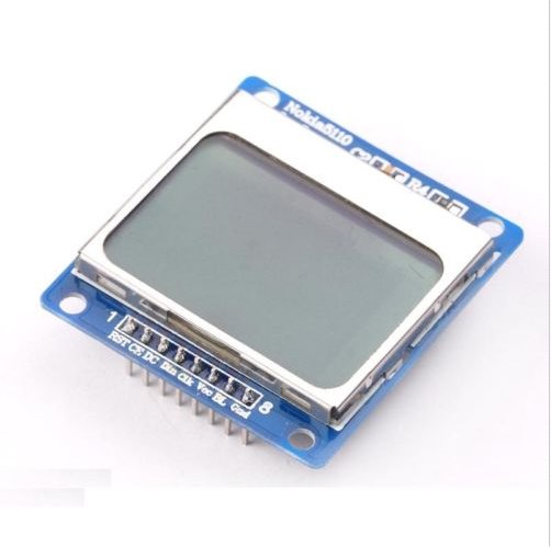
This is a very cheap and easy to use outdoor visible LCD display with led backlight, sourced mainly from recycled Nokia 5110 dumb phones. Many units such as the one pictured above (Banggood) have some small scratches from their previous lives, but the under $2 price makes them very popular for hobbyists. Also available from https://www.sparkfun.com
Price Under $2 each (Banggood, Ebay). More from Sparkfun, but perhaps their displays are not scratched ?
Operating voltage: 3 - 5v
Resolution: 48 rows and 84 columns
Operating Current without backlight: ≤200 µA
Blue backlight
Uses the Philips PCD8544 graphics controller chip.
3v logic, Google if you want to use 5v logic from ancient Arduinos
Documentation
Nokia 5110 display: https://www.sparkfun.com/datasheets/LCD/Monochrome/Nokia5110.pdf
Philips PCD8544 graphics controller chip: https://www.sparkfun.com/datasheets/LCD/Monochrome/Nokia5110.pdf
Synopsis
In this page I describe how to get a Nokia 5110 lcd display up and running, at least to test stage using Mecrisp-Stellaris, with code and Logic Analyser pictures of the data and control signals. This is for completeness as it’s actually very easy to get it working once you know what needs to be done. The trick is acquiring accurate knowledge about this display.
Even if you don’t use Forth, this may assist you the first time you run one of these dispays up.
Research
Whilst there are a great many YouTube articles regarding the 5110 lcd, the bulk are for Arduino and short of many critical details given their fondness for recycling C libraries made by others which are also short on details.
A special thank you to Julian Ilet for his excellent 5110 youtube videos: https://www.youtube.com/watch?v=RAlZ1DHw03g, without which I’d have taken considerably more time to get to this point.
Software Design
Create and send the correct 5110 initialization signals
Bit Bang serial commands to the display using a software SPI
Note
The 5110 requires the ‘SPI’ protocol of DATA and CLOCK. DATA is clocked in on the RISING EDGE of the CLOCK signal, so if the DATA line is LOW on the RISING CLOCK edge, then a DATA LOW is clocked in. The Bit Banging is done in code, and is quite simple.
Hardware and Software Used
FreeBSD 11.1 OS, Linux, OSX should work fine also
STM32F051, 32 bit CortexM based as standard in a STM32F0 Discovery Board
Banggood model SKU078678 (2014) using a second hand Nokia 5110 LCD display.
Open Bench Logic Sniffer http://dangerousprototypes.com/docs/Open_Bench_Logic_Sniffer. A $5 Chinese Saleae logic 8 channel clone would be fine as well.
Pulseview and Sigrok FLOSS logic analyser software https://sigrok.org/wiki/Main_Page
Pinouts and Signals
5110 Display pinouts and STM32F051 GPIO’s used
PIN |
FUNCTION |
GPIO |
WIRE COLOR |
NOTES |
|---|---|---|---|---|
1 |
RST |
PB2 |
ORANGE |
Reset, active LOW. Internally this is the junction of a 10k pull up and a 104 cap to 0v. |
2 |
CE |
PB3 |
YELLOW |
Chip Enable, active LOW |
3 |
DC |
PB4 |
GREEN |
D=DATA, C=COMMAND Mode. Whe HIGH, you’re in DATA mode, LOW and you’re in COMMAND mode. |
4 |
DATA |
PB5 |
BLUE |
|
5 |
CLK |
PB6 |
PURPLE |
Active rising edge |
6 |
VCC |
3v |
GREY |
From the ‘3v’ pin on the STM32F0 Discovery Board |
7 |
LIGHT |
PB7 |
WHITE |
Back Light, Active HIGH. |
8 |
GND |
0v |
BLACK |
The very First Test
Make sure the LED Backlights work. If you have a different type of 5110 lcd display, your BL (backlight) pin may need to be LOW to work, unlike mine which are HIGH.
5110 Essential Initialization
Warning
Without the following sequence, the 5110 display will never display anything.
LCD Init commands
Warning
Sequence order must be followed top to bottom.
Hex |
Name |
Description |
|---|---|---|
n/a |
Rst |
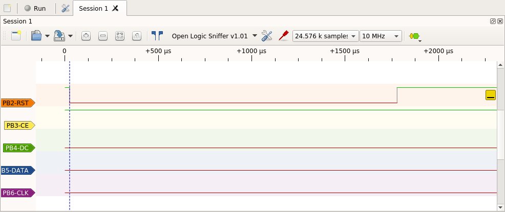
Low going pulse of about 1.7 milli seconds |
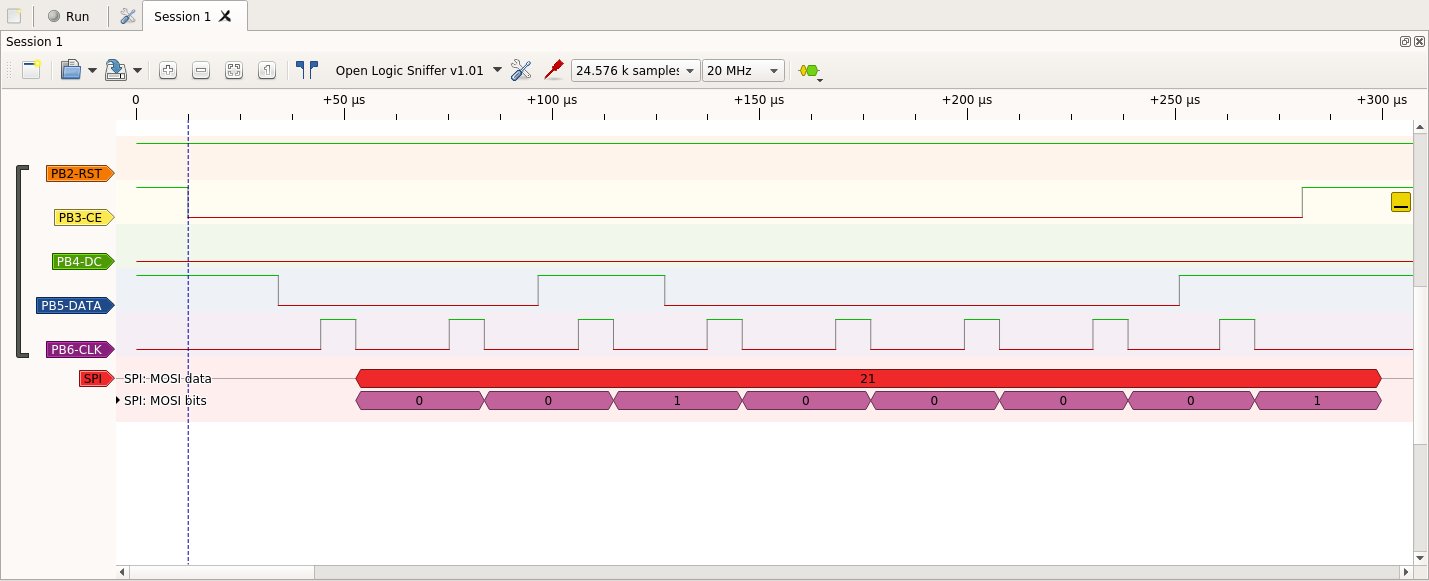
$21 |
Extended |
serial command: Lcd extended command mode |
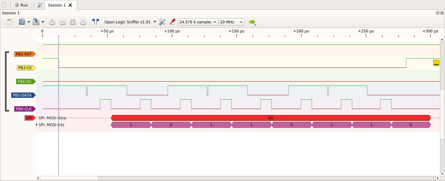
$B6 |
Contrast |
serial command: Lcd set contrast command |
4 |
Coeficient |
serial command: Lcd set temperature coeficient command |
$14 |
Bias |
serial command: Lcd set bias command |
$20 |
Basic |
serial command: Lcd basic command mode |
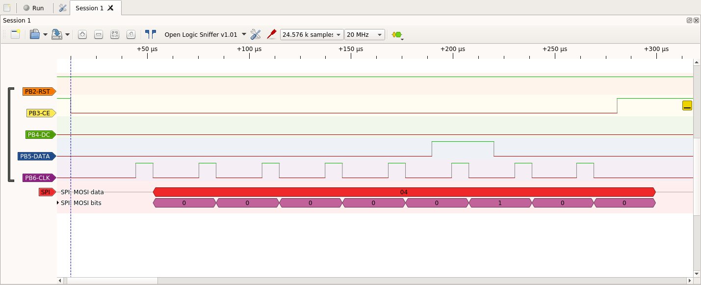
Logic Timing Diagram
These are what I really wanted when I started the project because a picture is worth a thousand words, expecially when signal timing is unclear.
Vcc is 3v and has been on a long time before any of the signals below are sent
All serial commands consist of data and a clock, and are sent Most Significant Bit (MSB) first
The Logic Analyser is triggered when CE ( Chip Enable, active LOW ) goes LOW and is signified by the dashed blue vertical line on each picture.
Lcd Reset
Could be shorter than 1.7 milli seconds I imagine, but realy short, i.e. with zero delay will not start the display.
Extended Command ($21)
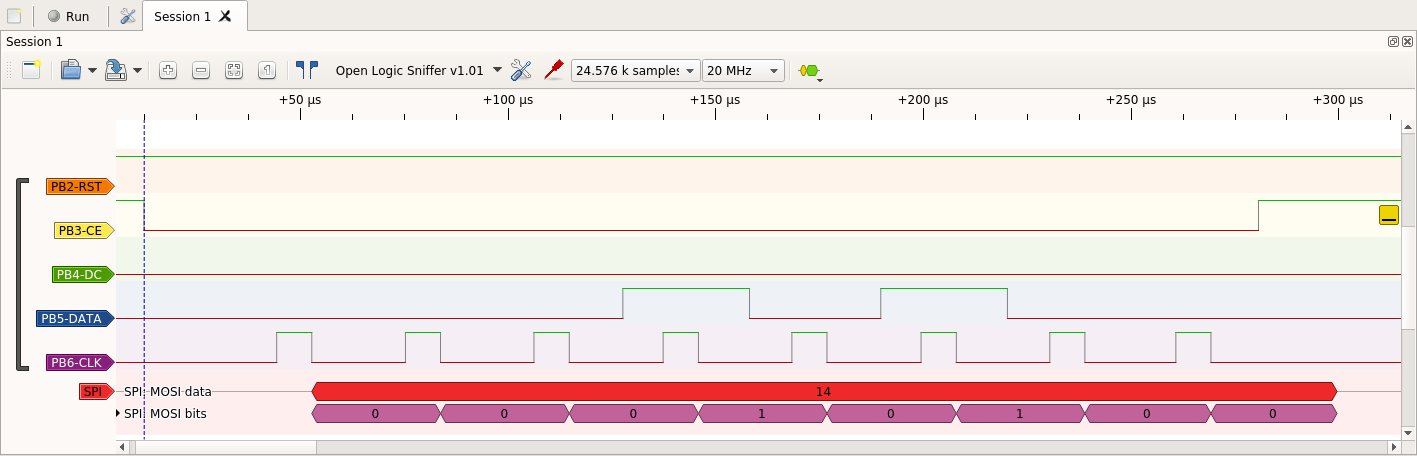
Contrast Command ($B6)
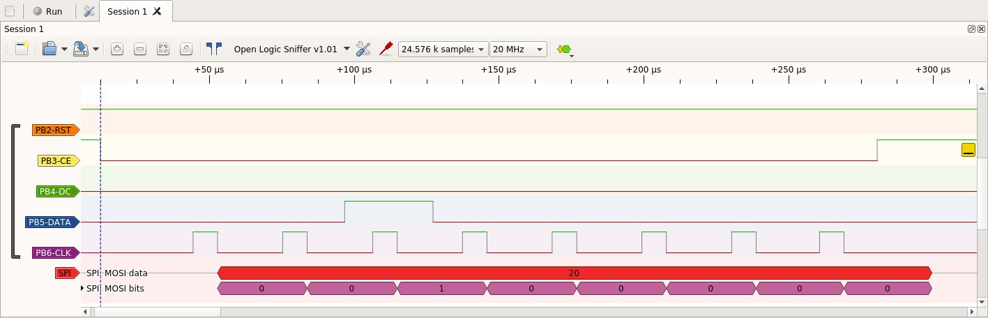
Temperature Coefficient Command(4)
Bias Command ($14)
Basic Command ($20)
Note
This concludes the basic Init process. After the next command is run, all of the Pixels should be on.
All Pixels On Command (9)
Note
There are many kinds of Nokia 5110 Lcd displays on eBay, and some require different BIAS and COEFFICIENT values. If your display is still blank after running the commands above, I recommend you search online for settings known to work with your display.

Photo of all pixels on
From the Julian Ilet video linked above.
Forth Code
Standalone, no other files needed. Just upload to a STM32F0 Discovery Board connected to a 5110 LCD.
Will turn on All Pixels
