Out Of Date QFN Chips
In September 2021 I ordered 150 off Ti MSP430G2201 16 pin QFN MCUs from my preferred supplier at $0.38 AUD each.
However these chips are almost unsolderable because (in my opinion) they are way past their use-by-date and/or the contacts are just some short life electroplated coating. Texas Instruments, I’m surprised at you if these are indeed bona fide chips from your factories.
I don’t blame the supplier because their prices, service and shipping are outstanding. This does however illustrate yet another trap when buying chips in October 2021 during the Great Chip Shortage, namely that suppliers are scraping the very bottom of the barrel for parts.
These chips would NOT be suitable for any P&P production runs based on my extensive experience in that industry, so buyer beware.
However they are OK for a hobbyist if the pins are cleaned up and pre tinned before use.
MSP430G2201 16 pin QFN
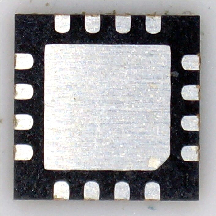
This is a typical picture of these chips and you can see brownish oxidisation where the pins have been cut during manufacturing and the white dots of corrosion ? everywhere.
Even with lots of liquid flux I couldn’t get the solder to stick well and my first attempt was utterly FOOBAR.
The chips are tiny being 4 * 4 * 1 mm in size.
Note
The coating on the pins and the centre square isn’t solder, it’s some kind of electrochemical coating, probably a lot cheaper than tinning. Pay particular attention to the obvious striations on the pins and centre area.
Advice
I received advice (thanks!) from two posters on https://sourceforge.net/p/mecrisp/discussion/general/thread/0c5cc94ee1/?limit=25#cf6b
Maciek
Take a regular, cheap envelope or a cheap sheet of copy paper, the cheapest and ugliest the better.
Place that piece of paper on a table or any other hard and even surface. Then place that QFN chip on that piece of paper, copper down, text markings up. Place your finger on that chip and gently rub it on the paper making circular moves a couple of times. Do not press the chip too hard. Examine the contacts with the loupe and maybe repeat the procedure if not satisfied the first time you tried. Then put some tiny amount of flux gel on that copper side of the chip and spread it evenly, and, if you have means to do so, heat it up to a melting point of that flux gel.
That’s it.
The chip will solder like new. At least that’s my personal experience and I have not wasted a single chip this way and soldered many. In fact, all of my QFN chips are long past their use by date but still perfectly usable with this technique.
Note
I used ordinary cheap white phopocopier paper.
Maciek Method Results
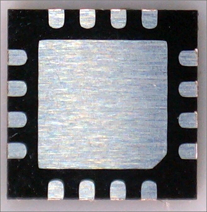
I could feel the burrs on the outside of the chip pins wearing down during the paper process. I found I needed to rub the chip lightly about 12 times in circles of 3” diameter on the paper, but pressure and paper type are variables here so your mileage will vary.
Note how the initial brownish corrosion now has a shiny copper color and the white dots are mostly gone ? More rubbing on the paper would no doubt improve this.
Peter Jakacki
… At the very most you would use a soft eraser perhaps. …
Jakacki Method Results
The marks in the centre are from where I used tweezers to hold the chip down while rubbing the eraser edge on the chip pins.
Application
I used each method on these chips.
Both methods work but Maciek’s method was far easier to apply.
These chips are tiny. It’s far easier to place the chip contact down on the paper and push it gently around in circles under a finger than holding the tiny chip in tweezers while attempting to rub the contacts with an eraser.
Ready to be Tinned
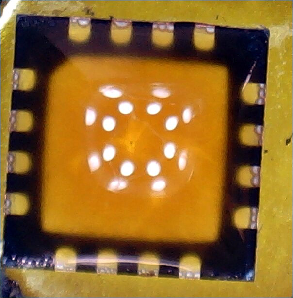
Swimming in liquid flux. This is exactly the same flux method I used with the first (FOOBAR) result. Flux alone won’t do the job.
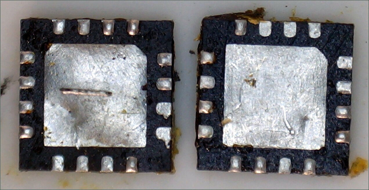
Results Compared
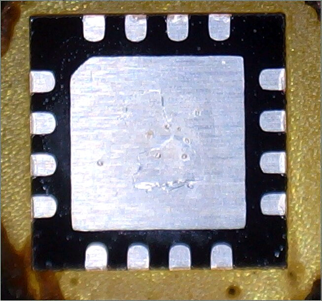
You can be the judge of the results, Maciek’s method was used on the leftmost chip marked with a “-”, and Peter Jakacki’s method on the right. The chips were extensively cleaned afterwards with Toluene and a toothbrush, but at this magnification level every flaw is obvious.
Tools Used
Very old 1mm diameter resin cored leaded solder used here along with a old 3mm wide shovel tip in a Thermaltronics TMT9000S-2 soldering station.
STM32F051 Comparison
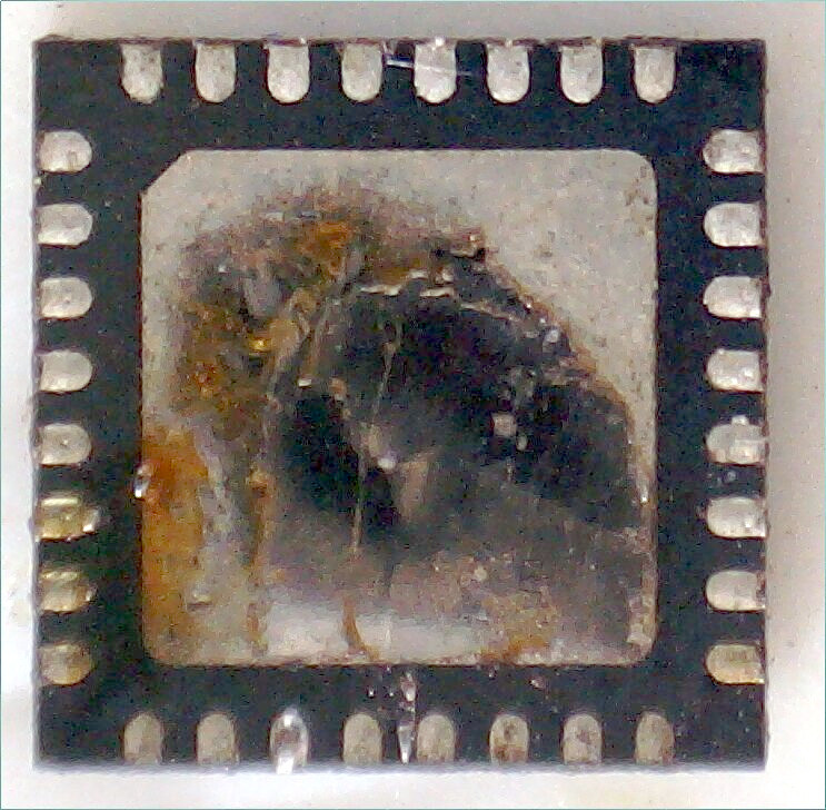
In 2014 I bought a number off STM32F051 MCU’s and this particular chip has been sitting in a parts box for 7 years, it hasn’t been cleaned or otherwise touched.
I used exactly the same tip and solder as with the Ti chips above but NO LIQUID FLUX and the solder virtually LEAPT onto the chip and some of the pins. This chip has ZERO soldering problems.
Why the massive difference between soldering the two types of chip?
STM32F Granulated Solder Coating
For one thing the STM32 surface is different to the Ti chips, it looks granulated, like a fine dusting of solder was applied. Unfortunately this isn’t apparent in the picture as my cheap USB microscope lacks the magnification, but I can easily see it in my 40+ binocular microscope.
Ti MSP340 Coating
The Ti chip coating is smooth and of electrochemical appearance by comparison containing striations which the STM32F051 does not.
