Source Documentation
My embedded Forth code can be pretty hard to read, especially when it’s full of CMSIS-SVD named register configs and binary numbers so as I’ve been developing my Mecrisp-Stellaris IDE and learning Forth I have also been experimenting with different documentation strategies.
Now there are a few “Forth Style Guides” around but they just don’t work for me, so in true Forth tradition, I’m trying to create what works best in my case.
In-Source Text : Configuration Code
It’s horrible, I agree. This code is all initialisation code, barely a step up from C headers and about as interesting. I haven’t been able to make this kind of source any prettier yet. Does it actually need to be ?
Each line has a comment automatically pulled from the CMSIS-SCD ‘description field’, and often additional comments of mine but for deeper knowledge you’ll have to consult the STM32F0 Reference Manual. ALL the information you need to do that is in this code, however embedded programming requires a intimate knowledge of the MCU peripheral hardware.
\ Tim6 related Words
: nvic_iser_setena-tim6 ( -- ) 1 17 lshift nvic_iser bis! ;     \ nvic_iser_setena   tim6
: nvic_icer_clrena-tim6 ( -- ) 1 17 lshift nvic_icer bis! ;     \ nvic_icer_clrena  tim6
: nvic_icpr_clrpend-tim6 ( -- ) 1 17 lshift nvic_icpr bis! ;    \ nvic_icpr_clrpend  tim6
: tim6_cnt@ ( -- ) tim6_cnt h@ ;  \ tim6_cnt_cnt   16 bit counter value
: tim6_cr1_opm ( -- ) %1 3 lshift tim6_cr1 hbis! ;      \ tim6_cr1_opm one-pulse mode
: tim6_cr1_cen ( -- ) %1 0 lshift tim6_cr1 hbis! ;      \ tim6_cr1_cen    counter enable
: tim6_cr1_cdis ( -- ) %1 0 lshift tim6_cr1 hbic! ;     \ tim6_cr1_cen    counter disable
: tim6_dier_uie ( -- ) %1 0 lshift tim6_dier hbis! ;    \ tim6_dier_uie        update interrupt enable
: tim6_sr_uif ( -- ) %1 0 lshift tim6_sr hbic! ;        \ tim6_sr_uif  clear tim6 int pending flag
: tim6_egr_ug ( -- ) %1 0 lshift tim6_egr hbis! ;       \ tim6_egr_ug  update generation

: tim6.prescale ( low-auto-reload-value -- ) \ Don't cause interrupt. PSC does not get 'active' until the second update event
  tim6_arr h!              \ low auto-reload value
  tim6_egr_ug              \ update generation: (causes a interrupt when run) but loads ARR into shaddow register!
  tim6_sr_uif              \ clear tim6 int pending flag after running tim6_egr_ug
  tim6_dier_uie            \ update interrupt enable
;

: tim6.int.handler ( -- )
  nvic_icpr_clrpend-tim6                 \ clear pending iser for tim6
  tim6_sr_uif                            \ clear tim6 int pending flag
  tim6_cr1_cdis                          \ counter disable
  nvic_icer_clrena-tim6                  \ disable tim6 interrupt or dropping power to the LMT01 will re-trigger it
  green-off                              \ END COUNT WINDOW
  lmt01-x.power.off
  lmt01-x.count @ total.pulses.counted ! \ total.pulses.counted now contains valid lmt01 count
  1 ready.flag !                         \ it's safe to read total.pulses.counted now
  nvic_iser_setena-tim6                  \ re-enable tim6 iser
  nvic_iser_setena-exti0_1               \ re enable exti0_1 iser ( won't work without this )
;
In-Source Text : Program Code
I’m pretty happy with this method of documentation and if the names of Words called are very descriptive, the source is almost self documenting which has always been a Forth feature.
: read.sensor ( sensor # -- error | stable data )      \ Select and read sensor, test for error
   0 lmt01-x.count !
   0 total.pulses.counted !
   0 ready.flag !
      case                                     \ power up selected sensor
        1 OF lmt01-1.power.on ENDOF
        2 OF lmt01-2.power.on ENDOF
        3 OF lmt01-3.power.on ENDOF
        ." No such sensor !! "                 \ sensor not implemented fall thru warning
      endcase
   green-on                                    \ START COUNT WINDOW
   tim6_cr1_cen                                \ enable timer6 (end of timer kills the power to the lmt01)
      begin                                    \ loop until total.pulses.counted is stable
        pause                                  \ 'pause' hands control back to the cooperative multitasker
        ready.flag @ 1 =                       \ has ready.flag been set by tim6.int.handler ?
      until                                    \ total.pulses.counted now has valid count and can be read
      lmt01-fault? if ." lmt01-fault ! "
      then
 ;
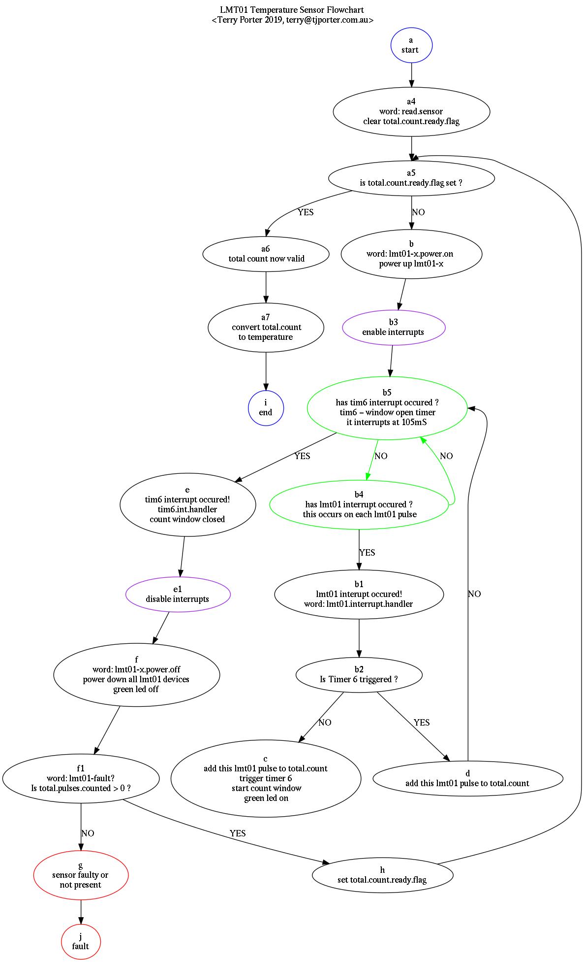
Flowcharting
I’m exploring using Flowcharting for Forth PROGRAM documentation. Something that explains what all the sourcecode does in one big picture. It takes ages, especially after the fact and when trying to work out what the hell I wrote several months ago, so I’m trying to make flowcharting the INITIAL part of my Forth design process.
But here is the CATCH ..
I love just jumping straight into Forth coding, I mean that’s the beauty of the Forth paradigm, “try it before you buy it”. By this I mean with Forth I can just change some registers in near real time and observe the effect, be it turning a stepper motor or checking the byte order of a CRC generating peripheral. Using this method my code just seems to build itself.
The C methodology is studying the databook with infinite care, meticulously craft all my code, which then bombs because I misread the databook or it was ambiguous. So out with the debugger or scrutinise my code, then rinse and repeat.
wierd fact
When I used to program only in Machine Code (in the early 80’s), I flowcharted my programs first and the two technologies seemed to smoothly meld together. When I finally obtained a decent Motorola 6800 Assembler it was exactly the same, but when I moved up to C programming I never flowcharted again, I just couldn’t do it, some mental block stopped me. Perhaps C and flowcharts just don’t work together, at least in my head ?
So combining Flowcharting with Forth source code development in a easy and fun way is my current challenge.
Graphviz
I flowchart with Graphviz Dot and it’s built into my Forth development system. When I hit Make after editing the flowchart source, it’s compiled into a jpeg and the picture of the flowchart displayed for my review.
There are a few Diagrammers that run under Unix that use Java or C with some widget set that are mouse driven but I find them all too tedious and even more work with complex flowcharts than Graphviz.
I’m finding the Graphviz flowchart source a bit tedious also but I like the results. What do you think ?
Flowchart Source Code
digraph {
// title
    labelloc="t";
    label="LMT01 Temperature Sensor Flowchart\n <Terry Porter 2019, terry@tjporter.com.au>";

A [color=blue,label="a\nstart "]
A4[label="a4\nword: read.sensor\n clear total.count.ready.flag "]
A5[label="a5\n is total.count.ready.flag set ? "]
A6[label="a6\n total count now valid"]
A7[label="a7\n convert total.count\nto temperature"]
B [label="b\nword: lmt01-x.power.on \npower up lmt01-x"]
B1[label="b1\nlmt01 interupt occured!\nword: lmt01.interrupt.handler"]
B2[label="b2\nIs Timer 6 triggered ?"]
B3[color=purple,label="b3\nenable interrupts"]
B4[color=green,label="b4\nhas lmt01 interrupt occured ?\n this occurs on each lmt01 pulse"]
B5[color=green,label="b5\nhas tim6 interrupt occured ?\n tim6 = window open timer\n it interrupts at 105mS "]
C [label="c\nadd this lmt01 pulse to total.count\ntrigger timer 6\n start count window\n green led on"]
D [label="d\nadd this lmt01 pulse to total.count"]
E [label="e\ntim6 interrupt occured!\ntim6.int.handler\ncount window closed"]
E1[color=purple,label ="e1\ndisable interrupts"]
F [label="f\nword: lmt01-x.power.off\npower down all lmt01 devices\ngreen led off"]
F1[label="f1\nword: lmt01-fault?\nIs total.pulses.counted > 0 ?"]
G [color=red,label="g\nsensor faulty or\nnot present"]
H [label="h\nset total.count.ready.flag"]
I [color=blue,label="i\nend"]
J [color=red,label="j\nfault"]
A    -> A4
A4   -> A5
A5   -> B  [label="NO"]
A5   -> A6:n [label="YES"]
A6   -> A7
A7   -> I
B    -> B3
B1   -> B2
B2   -> C  [label="NO"]
B2   -> D  [label="YES"]
B3   -> B5
B4   -> B1 [label="YES"]
B4:e -> B5 [color=green,label="NO"]
B5   -> B4 [color=green,label="NO"]
B5   -> E  [label="YES"]
D    -> B5:e [label="NO"]
E    -> E1
E1   -> F
F    -> F1
F1   -> G   [label="NO"]
F1   -> H   [label="YES"]
H    -> A5:n
G    -> J
}
Flowchart Picture
This picture is compiled automatically by “dot” and 99% of the time it’s a great layout. On occasion I have to force a line to a particular node ‘edge’ but that’s rare and I try not to do it. Having said that, there are three such instances here, but I wanted a pleasing graph for this page :)
I don’t position any of the nodes, ever. I leave that entirely up to Graphviz. The whole idea is for super fast flowchart generation and minimal coding to get it.