Blue Pill Starter Kit (STM32F103)
Warning
The Blue Pill Starter Kit (STM32F103) is no longer developed and has been replaced by the Bluepill-Diagnostics which is far better and has almost all the same facilities.
Note
Even tho it’s no longer developed, the information is very useful so if you find something is broken please let me know and I’ll fix it.
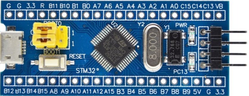
The Blue Pill board is very popular due to the very low cost and many new Forth users who are not familiar with the MCU used in this board find that it’s a major task to even get a LED on the board to turn on/off.
The MCU in the Blue Pill is quite old and lacks the capabilities of more modern STM chips, however it is still extremely complex and the new user will soon be researching a 1096 page Technical Reference PDF to understand how everything works.
Do have a quick look at my anti Blue Pill rant especially if you have not yet bought one ?
This Starter Kit contains files to upload into your Blue Pill and a tutorial to help make mastering the STM32F103 MCU in general, and the Blue Pill LED in particular a bit easier. It covers basic RCC and GPIO usage. Everything is freely available under Open Source Licenses.
You only need a serial terminal and file editor on your PC, no GCC, no GDB, no Eclipse, no massive GigaByte software downloads. This will run on any OS in a serial terminal.
With Forth on a Blue Pill, a complete INTERACTIVE development system, including the Starter Kit files is built into the MCU using only 26.5 KB of Flash.
Note
The methods shown here are just ONE WAY to do this. Forth can do this any way YOU want!
See also
Prerequisites
Terminal
Connect a 3.3v/usb dongle to USART1 pins PA9 (TX)—> Dongle (RX) PA10 (RX) —> Dongle (TX)
1) Mecrisp-Stellaris must be loaded onto your Blue Pill and running
So when you reboot the board you get a message similar to this on the terminal.
Mecrisp-Stellaris RA 2.5.1 for STM32F103 by Matthias Koch
Download Mecrisp-Stellaris RA 2.5.1
You can DOWNLOAD the same self booting Mecrisp-Stellaris binary file I use for this tutorial HERE.
Problems Flashing
If you need help flashing Mecrisp-Stellaris onto your Blue Pill, see here.
What is all this about anyway ?
If you have just stumbled across this page and have no idea what any of this is about, this link may help.
2) You must be able to upload Forth files via your terminal
Without experiencing the infamous, and easily fixed “lockup”. see Common Problems Page
3) You should have the STM32F103xx Reference Manual PDF open
The manual I’m referring to is Doc ID 13902 Rev 14 dated October 2011, DOWNLOAD it HERE: Technical Reference PDF, yes it’s 1096 pages.
The Kit
The kit contains 7 files:
File |
Description |
Download Link |
|---|---|---|
Technical Reference |
STM Doc ID 13902 Rev 14 dated October 2011 |
|
1b.fs |
Print support file, must be loaded first |
|
memmap.fs |
Memory map file, must be loaded second |
as above |
bitfields.fs |
Configuration templates file, not to be loaded. copy and paste selections |
as above |
memstat.fs |
This Word tells you how much Flash and Ram you have used |
as above |
words4.fs |
Lists all the Words (programs, subroutines, functions) on your Blue Pill |
as above |
f103-developer-image.c9ebc3e9d6.words4.txt |
Words used in this kit |
as above |
Using the Kit
Downoad the four files listed below from HERE:. Note there are other files which may be helpful/interesting.
1b.fs
memmap.fs
memstat.fs
words4.fs
into your Blue Pill via the Mecrisp-Stellaris terminal in the exact sequence shown here top to bottom. These should load into Flash without any errors and finish with a “ok” at the cursor.
Note
If you mess up here, perhaps load everything twice and start getting “Redefine” Warnings (this isn’t a ERROR) you can easily delete everything you have loaded (but not Mecrisp-Stellaris) with the command “eraseflash” and start again.
Utilities
First, a couple of useful utility files, memstat.fs which shows how much Flash and RAM you have and words4.fs which shows all the Forth programs loaded (and available). Both of these are now loaded into your Blue Pill.
Memstats
All the doc I’ve read claims the Blue Pill chip has 20KB of RAM, so that’s what the Word “free” assumes it has.
The actual amount of Flash on your chip is stated in a register, so “free” looks that up. My chip (not a Blue Pill) only has 65KB Flash. Your results may be different as I read that many Blue Pills have 128KB Flash MCU’s.
My LC Mini
free

free (bytes)
FLASH.. TOTAL REPORTED: 65536 USED: 26460 FREE: 39076
RAM.... TOTAL PRESET: 20000 USED: 628 FREE: 19372
Note
Mecrisp-Stellaris, and all the Starter Kit files are loaded into Flash so the small amount of RAM shown used is for Mecrisp-Stellaris.
This shows that the ENTIRE Mecrisp-Stellaris INTERACTIVE Forth program plus the five programs of the Starter Kit use only 26.5 KiloBytes on your chip leaving at least 39KB of Flash ( for a STM43F103 with 64KB total Flash) and 19.3KB of RAM available for user programs.
In the EMBEDDED Forth world, 39KB of Flash is a MASSIVE amount of memory. If your Blue Pill has 128KB of Flash, then you would have 103 KB of Flash free!
Mecrisp-Stellaris Forth is the SMALLEST complete INTERACTIVE EMBEDDED PROGRAMMING LANGUAGE for STM32 that is available under the GPL to my knowledge.
A Blue Pill With a NON STM32F103 MCU ?
Thanks to ‘Michael Jeffery’ for this feedback. He has a STM32F103 clone, the CKS CS32F103
free (bytes)
FLASH.. TOTAL REPORTED: 131072 USED: 42988 FREE: 88084
RAM.... TOTAL PRESET: 20000 USED: 1072 FREE: 18928
Words4
This utility displays the Words (also known as programs, subroutines or functions in other programming languages) currently loaded and available on your Blue Pill.
words4

--- Mecrisp-Stellaris RA 2.5.1 ---
2dup                2drop               2swap               2nip
2over               2tuck               2rot                2-rot
2>r                 2r>                 2r@                 2rdrop
d2/                 d2*                 dshr                dshl
dabs                dnegate             d-                  d+
s>d                 um*                 m*                  ud*
udm*                */                  */mod               u*/

... lots more Words ...

irq-tim7            irq-usbfs           --- Flash Dictionary ---
b32loop.            b32sloop.           1b.                 bin.
RCC                 RCC_CR              RCC_CFGR            RCC_CIR
RCC_APB2RSTR        RCC_APB1RSTR        RCC_AHBENR          RCC_APB2ENR
RCC_APB1ENR         RCC_BDCR            RCC_CSR             RCC_CR.
RCC_CFGR.           RCC_CIR.            RCC_APB2RSTR.       RCC_APB1RSTR.
RCC_AHBENR.         RCC_APB2ENR.        RCC_APB1ENR.        RCC_BDCR.
RCC_CSR.            RCC.                GPIOA               GPIOA_CRL
GPIOA_CRH           GPIOA_IDR           GPIOA_ODR           GPIOA_BSRR
GPIOA_BRR           GPIOA_LCKR          GPIOA_CRL.          GPIOA_CRH.
GPIOA_IDR.          GPIOA_ODR.          GPIOA_BSRR.         GPIOA_BRR.
GPIOA_LCKR.         GPIOA.              GPIOB               GPIOB_CRL
GPIOB_CRH           GPIOB_IDR           GPIOB_ODR           GPIOB_BSRR
GPIOB_BRR           GPIOB_LCKR          GPIOB_CRL.          GPIOB_CRH.
GPIOB_IDR.          GPIOB_ODR.          GPIOB_BSRR.         GPIOB_BRR.
GPIOB_LCKR.         GPIOB.              GPIOC               GPIOC_CRL
GPIOC_CRH           GPIOC_IDR           GPIOC_ODR           GPIOC_BSRR
GPIOC_BRR           GPIOC_LCKR          GPIOC_CRL.          GPIOC_CRH.
GPIOC_IDR.          GPIOC_ODR.          GPIOC_BSRR.         GPIOC_BRR.
GPIOC_LCKR.         GPIOC.              RCC_APB2ENR_ADC1EN  RCC_APB2ENR_ADC1-DIS
ADC1EN?             GPIOC_CRH_MODE13    GPIOC_CRH_MODE13-clear
GPIOC_CRH_CNF13     GPIOC_CRH_CNF13-clear
GPIOC_BSRR_BS13     GPIOC_BSRR_BR13     GPIOC_13_clear      GPIOC_13_output
pc13.on             pc13.off            ledon               ledoff
flashfree           ramfree             free                words4
 ok.
Go ahead and type in “free” or “words4” into your terminal (don’t forget to hit the ENTER key after each Word), have a play with them, get comfortable with using them.
Note
“free” and “words4” are just TWO of many, many diagnostic and development Words available to Mecrisp-Stellaris Forth users.
STM32F103 Basics
Power up/reset
At power-up and reset the STM32F103 has all the internal Peripherals switched off and normally only the internal RC clock is running at this time. However if you have Mecrisp-Stellaris running on your Blue Pill, all the important configuration HAS ALREADY BEEN DONE and vital Peripherals are already ENABLED and configured for you.
RCC
The STM32F has one VERY IMPORTANT REGISTER GROUP named “RCC” which stands for “Reset and Clock Control”. The RCC controls all the Peripherals, whether they are ON OR OFF plus other important settings.
Which Peripherals are ENABLED on your Blue Pill ?
Turn to page 142 of the
Technical Reference PDFand you will see the following table.
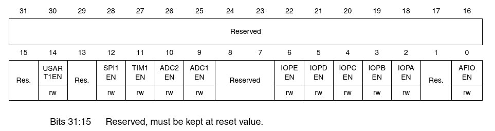
APB2 PERIPHERAL CLOCK ENABLE REGISTER (RCC_APB2ENR)
2) now type the following command into your terminal:
RCC_APB2ENR.
Note
the “.” period at the end of the Register name, this is important.
And you will get the following Register Pretty Print which shows the values of the “Bitfields” in the RCC_APB2ENR register on your Blue Pill RIGHT NOW, in real time.
RCC_APB2ENR.
RCC_APB2ENR (read-write) $0000403D
3|3|2|2|2|2|2|2|2|2|2|2|1|1|1|1|1|1|1|1|1|1|
1|0|9|8|7|6|5|4|3|2|1|0|9|8|7|6|5|4|3|2|1|0|9|8|7|6|5|4|3|2|1|0
0 0 0 0 0 0 0 0 0 0 0 0 0 0 0 0 0 1 0 0 0 0 0 0 0 0 1 1 1 1 0 1
ok.
Analysis
Comparing the picture and the print on your screen we can see that all the GPIO ports and USART1 have been ENABLED already by Mecrisp-Stellaris as part of its initilization routine.
Bit |
Enabled? |
Mnemonic |
Description |
|---|---|---|---|
0 |
Y |
AFIOEN |
Alternate Functions Enable |
2 |
Y |
IOPAEN |
GPIOA ENABLE |
3 |
Y |
IOPBEN |
GPIOB ENABLE |
4 |
Y |
IOPCEN |
GPIOC ENABLE |
5 |
Y |
IOPDEN |
GPIOD ENABLE |
9 |
N |
ADC1EN |
Analog to Digital Converter 1 ENABLE |
14 |
Y |
USART1EN |
USART1 ENABLE |
Self Test
Is TIM1 ENABLED ?
ADC1
ADC1 is NOT enabled, how can we enable ADC1 to use it ?
Bitfields.fs
File bitfields.fs was automatically generated to make configuring Bitfields easier than having to read the Datasheets and work out every single thing.
bitfields.fs is a TEMPLATE collection, the Word names are automatically generated and usually changed by the programmer (you) to suit the purpose at hand.
Each template in bitfields.fs is designed to SET a BIT or BITS using the “BIS!” Word. This is changed if RESETTING (BIC!) or TESTING (BIT@) is required instead.
Because the contents of bitfields.fs are automatically generated from CMSIS-SVD data they make use of the “LSHIFT” command which SHIFTS BITS LEFT into their CMSIS-SVD specified bit positions.
Note
Check the Dictionary for what BIS!, lshift, BIC! and BIT@ actually do.
Open bitfields.fs in your editor and search for “ADC1EN”. This spelling is ARM CMSIS-SVD compliant. Your search will find this line:
: RCC_APB2ENR_ADC1EN %1 9 lshift RCC_APB2ENR bis! ; \ RCC_APB2ENR_ADC1EN ADC 1 interface clock enable
The name of the Word is “RCC_APB2ENR_ADC1EN” which is simply formed from the ARM CMSIS-SVD FILE for this chip. As written, this Word when executed on the MCU will set BIT 9 of the RCC_APB2ENR Register, which will ENABLE ADC1. Don’t enter anything, RCC_APB2ENR_ADC1EN has been previously loaded with “bluepill.support.fs”.
Enabling ADC1
Now execute RCC_APB2ENR_ADC1EN
RCC_APB2ENR_ADC1EN ok.
Examine RCC_APB2ENR again and BIT 9 is now SET, ENABLING ADC1.
RCC_APB2ENR.
RCC_APB2ENR (read-write) $0000423D
3|3|2|2|2|2|2|2|2|2|2|2|1|1|1|1|1|1|1|1|1|1|
1|0|9|8|7|6|5|4|3|2|1|0|9|8|7|6|5|4|3|2|1|0|9|8|7|6|5|4|3|2|1|0
0 0 0 0 0 0 0 0 0 0 0 0 0 0 0 0 0 1 0 0 0 0 1 0 0 0 1 1 1 1 0 1
ok.
Disabling ADC1
But this Starter Kit doesn’t have ADC1 support so it should be disabled now. To get support for all the Peripherals get the latest SVD2FORTH for this peripheral. Get https://sourceforge.net/projects/mecrisp-stellaris-folkdoc/files/SVD2FORTH-V3-STM32F103C8T6_6183770ed7.zip when you have worked thru to the end of this Starter Kit. NOTE: it needs Unix, Linux or FreeBSD to manipulate the files.
To disable ADC1 a new Word is needed, it’s a variation on RCC_APB2ENR_ADC1EN above with a name change and using BIC! instead of BIS! Don’t enter anything, RCC_APB2ENR_ADC1-DIS has been previously loaded with “bluepill.support.fs”.
: RCC_APB2ENR_ADC1-DIS %1 9 lshift RCC_APB2ENR bic! ;
Run RCC_APB2ENR_ADC1-DIS
RCC_APB2ENR_ADC1-DIS ok.
Read RCC_APB2ENR, NOTE: BIT 9 is now RESET, DISABLING ADC1
RCC_APB2ENR.
RCC_APB2ENR (read-write) $0000403D
3|3|2|2|2|2|2|2|2|2|2|2|1|1|1|1|1|1|1|1|1|1|
1|0|9|8|7|6|5|4|3|2|1|0|9|8|7|6|5|4|3|2|1|0|9|8|7|6|5|4|3|2|1|0
0 0 0 0 0 0 0 0 0 0 0 0 0 0 0 0 0 1 0 0 0 0 0 0 0 0 1 1 1 1 0 1
ok.
Those paying attention would have noticed that although we changed BIT 9 NONE OF THE OTHER BITS BITS IN RCC_APB2ENR WERE AFFECTED
Test ADC1 STATE ?
A Word can be made to TEST the state of the ADC1EN BIT, so that looking up the values of RCC_APB2ENR and searching for BIT 9 isn’t needed, this is how that Word could be designed. Don’t enter anything, ADC1EN? has been previously loaded with “bluepill.support.fs”.
: ADC1EN?   %1 9 lshift RCC_APB2ENR bit@
     if ." ADC1 is ENABLED "
        else ." ADC1 is DISABLED "
     then cr
;
Now run ADC1EN?
ADC1EN? ADC1 is DISABLED
Now ENABLE ADC1
RCC_APB2ENR_ADC1EN ok.
Rerun ADC1EN?
ADC1EN? ADC1 is ENABLED
ok.
Conclusion
Bitfields.fs contains Words with names auto-generated from the CMSIS-SVD which can be searched using names from the Technical Reference. Their Word names can be changed to reflect your usage and they can set BITS by default or be altered to RESET or even TEST bits as shown above.
Lots More Registers in RCC!
Q: But there are more Registers in the RCC, do I have to type the name for each one to see it ?
A: No, type the Group Name, ie “RCC” (don’t forget the trailing period)
rcc.

rcc.
RCC_CR () $00005083
3|3|2|2|2|2|2|2|2|2|2|2|1|1|1|1|1|1|1|1|1|1|
1|0|9|8|7|6|5|4|3|2|1|0|9|8|7|6|5|4|3|2|1|0|9|8|7|6|5|4|3|2|1|0
0 0 0 0 0 0 0 0 0 0 0 0 0 0 0 0 0 1 0 1 0 0 0 0 1 0 0 0 0 0 1 1

RCC_CFGR () $00000000
3|3|2|2|2|2|2|2|2|2|2|2|1|1|1|1|1|1|1|1|1|1|
1|0|9|8|7|6|5|4|3|2|1|0|9|8|7|6|5|4|3|2|1|0|9|8|7|6|5|4|3|2|1|0
0 0 0 0 0 0 0 0 0 0 0 0 0 0 0 0 0 0 0 0 0 0 0 0 0 0 0 0 0 0 0 0

RCC_CIR () $00000000
3|3|2|2|2|2|2|2|2|2|2|2|1|1|1|1|1|1|1|1|1|1|
1|0|9|8|7|6|5|4|3|2|1|0|9|8|7|6|5|4|3|2|1|0|9|8|7|6|5|4|3|2|1|0
0 0 0 0 0 0 0 0 0 0 0 0 0 0 0 0 0 0 0 0 0 0 0 0 0 0 0 0 0 0 0 0

RCC_APB2RSTR (read-write) $00000000
3|3|2|2|2|2|2|2|2|2|2|2|1|1|1|1|1|1|1|1|1|1|
1|0|9|8|7|6|5|4|3|2|1|0|9|8|7|6|5|4|3|2|1|0|9|8|7|6|5|4|3|2|1|0
0 0 0 0 0 0 0 0 0 0 0 0 0 0 0 0 0 0 0 0 0 0 0 0 0 0 0 0 0 0 0 0

RCC_APB1RSTR (read-write) $00000000
3|3|2|2|2|2|2|2|2|2|2|2|1|1|1|1|1|1|1|1|1|1|
1|0|9|8|7|6|5|4|3|2|1|0|9|8|7|6|5|4|3|2|1|0|9|8|7|6|5|4|3|2|1|0
0 0 0 0 0 0 0 0 0 0 0 0 0 0 0 0 0 0 0 0 0 0 0 0 0 0 0 0 0 0 0 0

RCC_AHBENR (read-write) $00000014
3|3|2|2|2|2|2|2|2|2|2|2|1|1|1|1|1|1|1|1|1|1|
1|0|9|8|7|6|5|4|3|2|1|0|9|8|7|6|5|4|3|2|1|0|9|8|7|6|5|4|3|2|1|0
0 0 0 0 0 0 0 0 0 0 0 0 0 0 0 0 0 0 0 0 0 0 0 0 0 0 0 1 0 1 0 0

RCC_APB2ENR (read-write) $0000403D
3|3|2|2|2|2|2|2|2|2|2|2|1|1|1|1|1|1|1|1|1|1|
1|0|9|8|7|6|5|4|3|2|1|0|9|8|7|6|5|4|3|2|1|0|9|8|7|6|5|4|3|2|1|0
0 0 0 0 0 0 0 0 0 0 0 0 0 0 0 0 0 1 0 0 0 0 0 0 0 0 1 1 1 1 0 1

RCC_APB1ENR (read-write) $00000000
3|3|2|2|2|2|2|2|2|2|2|2|1|1|1|1|1|1|1|1|1|1|
1|0|9|8|7|6|5|4|3|2|1|0|9|8|7|6|5|4|3|2|1|0|9|8|7|6|5|4|3|2|1|0
0 0 0 0 0 0 0 0 0 0 0 0 0 0 0 0 0 0 0 0 0 0 0 0 0 0 0 0 0 0 0 0

RCC_BDCR () $00000000
3|3|2|2|2|2|2|2|2|2|2|2|1|1|1|1|1|1|1|1|1|1|
1|0|9|8|7|6|5|4|3|2|1|0|9|8|7|6|5|4|3|2|1|0|9|8|7|6|5|4|3|2|1|0
0 0 0 0 0 0 0 0 0 0 0 0 0 0 0 0 0 0 0 0 0 0 0 0 0 0 0 0 0 0 0 0

RCC_CSR () $1C000000
3|3|2|2|2|2|2|2|2|2|2|2|1|1|1|1|1|1|1|1|1|1|
1|0|9|8|7|6|5|4|3|2|1|0|9|8|7|6|5|4|3|2|1|0|9|8|7|6|5|4|3|2|1|0
0 0 0 1 1 1 0 0 0 0 0 0 0 0 0 0 0 0 0 0 0 0 0 0 0 0 0 0 0 0 0 0
ok.
GPIO
Now onto the STM3F103 GPIO’s, this is the most confusing part of this tutorial and the age of this chip shows here in the unwieldy way the GPIO’s are configured. This is much simpler in later series such as Cortex-M0.
Subject to the specific hardware characteristics of each I/O port listed in the datasheet, each port bit of the General Purpose IO (GPIO) Ports, can be individually configured by software in several modes:
Input floating
Input pull-up
Input-pull-down
Analog
Output open-drain
Output push-pull
Alternate function push-pull
Alternate function open-drain
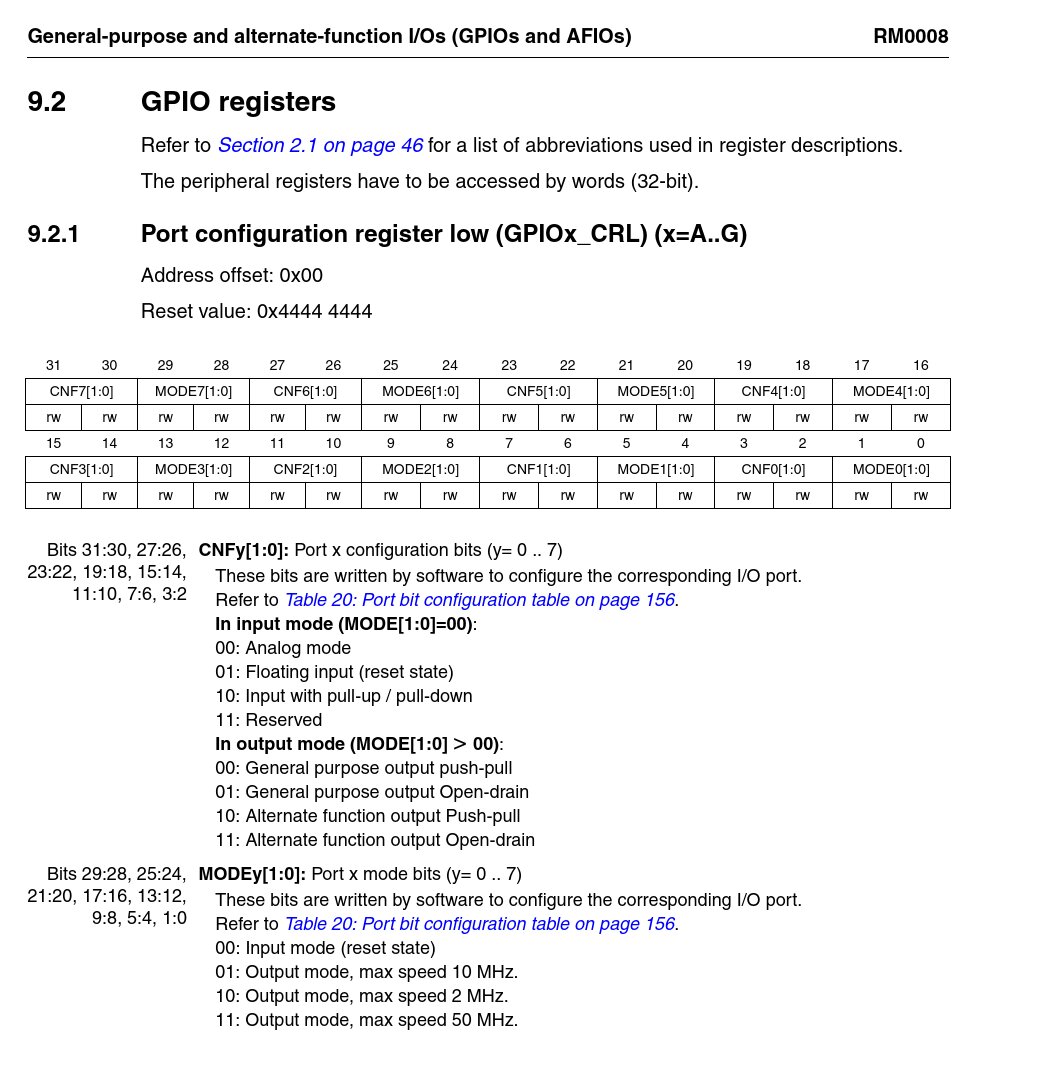
Turn to page 166 of the Technical Reference PDF and you will see the following table.
Port configuration register low (GPIOx_CRL)
Examine GPIOA
Now we know that the GPIO’s are ENABLED we can see the data in the GPIOA Peripheral the same way you saw the RCC data earlier.
GPIOA-CRL
As seen from the GPIOx_CRL table above, GPIOA_CRL controls the configuration of GPIOA bits 0 to 7. If you think that this is confusing, you’re right. Remember old chip Yet another reason not to use the Blue Pill.
GPIOA_CRL.
GPIOA_CRL (read-write) $44444444
3|3|2|2|2|2|2|2|2|2|2|2|1|1|1|1|1|1|1|1|1|1|
1|0|9|8|7|6|5|4|3|2|1|0|9|8|7|6|5|4|3|2|1|0|9|8|7|6|5|4|3|2|1|0
0 1 0 0 0 1 0 0 0 1 0 0 0 1 0 0 0 1 0 0 0 1 0 0 0 1 0 0 0 1 0 0
Note that there are eight GPIO’s here, GPIOA 0 to 7 and are all the same value as specified in groups of 4 bits, namely %0100 or HEX 0x4.
This means that GPIOA 0 to 7 are in their default value (after reset) which hasn’t been changed.
Decoding GPIO Config
First find the value in the MODE0 Bitfield, this will determine if the BIT is INPUT or OUTPUT.
Then look in CNF0 table either under INPUT or OUTPUT depending on the MODE0 value.
GPIOA_CRH
As seen from the table above, GPIOA_CRH controls the configuration of GPIOA BITS 7 to 15
GPIOA_CRH.
GPIOA_CRH (read-write) $888448A4
3|3|2|2|2|2|2|2|2|2|2|2|1|1|1|1|1|1|1|1|1|1|
1|0|9|8|7|6|5|4|3|2|1|0|9|8|7|6|5|4|3|2|1|0|9|8|7|6|5|4|3|2|1|0
1 0 0 0 1 0 0 0 1 0 0 0 0 1 0 0 0 1 0 0 1 0 0 0 1 0 1 0 0 1 0 0
Note that most of the GPIO’s are in the RESET DEFAULT configuration but with a few exceptions, namely BITS 8,9,12, 13 and 14.
BIT |
VALUE |
Mode |
|---|---|---|
9 |
0xA |
OUTPUT 2 MHz, ALTERNATE FUNCTION, PUSH-PULL |
10,13,14,15 |
0x8 |
OUTPUT 2 MHz, PUSH-PULL |
Self Test
Whats so special about GPIOA-9 ?
Print ALL GPIOA Contents
This is done in the same way as the RCC. above, only this time the Register Group is named “GPIOA”
gpioa.
GPIOA_CRL (read-write) $44444444
3|3|2|2|2|2|2|2|2|2|2|2|1|1|1|1|1|1|1|1|1|1|
1|0|9|8|7|6|5|4|3|2|1|0|9|8|7|6|5|4|3|2|1|0|9|8|7|6|5|4|3|2|1|0
0 1 0 0 0 1 0 0 0 1 0 0 0 1 0 0 0 1 0 0 0 1 0 0 0 1 0 0 0 1 0 0

GPIOA_CRH (read-write) $888448A4
3|3|2|2|2|2|2|2|2|2|2|2|1|1|1|1|1|1|1|1|1|1|
1|0|9|8|7|6|5|4|3|2|1|0|9|8|7|6|5|4|3|2|1|0|9|8|7|6|5|4|3|2|1|0
1 0 0 0 1 0 0 0 1 0 0 0 0 1 0 0 0 1 0 0 1 0 0 0 1 0 1 0 0 1 0 0

GPIOA_IDR (read-only) $0000BD7F
3|3|2|2|2|2|2|2|2|2|2|2|1|1|1|1|1|1|1|1|1|1|
1|0|9|8|7|6|5|4|3|2|1|0|9|8|7|6|5|4|3|2|1|0|9|8|7|6|5|4|3|2|1|0
0 0 0 0 0 0 0 0 0 0 0 0 0 0 0 0 1 0 1 1 1 1 0 1 0 1 1 1 1 1 1 1

GPIOA_ODR (read-write) $0000A400
3|3|2|2|2|2|2|2|2|2|2|2|1|1|1|1|1|1|1|1|1|1|
1|0|9|8|7|6|5|4|3|2|1|0|9|8|7|6|5|4|3|2|1|0|9|8|7|6|5|4|3|2|1|0
0 0 0 0 0 0 0 0 0 0 0 0 0 0 0 0 1 0 1 0 0 1 0 0 0 0 0 0 0 0 0 0

GPIOA_BSRR (write-only) $00000000
3|3|2|2|2|2|2|2|2|2|2|2|1|1|1|1|1|1|1|1|1|1|
1|0|9|8|7|6|5|4|3|2|1|0|9|8|7|6|5|4|3|2|1|0|9|8|7|6|5|4|3|2|1|0
0 0 0 0 0 0 0 0 0 0 0 0 0 0 0 0 0 0 0 0 0 0 0 0 0 0 0 0 0 0 0 0

GPIOA_BRR (write-only) $00000000
3|3|2|2|2|2|2|2|2|2|2|2|1|1|1|1|1|1|1|1|1|1|
1|0|9|8|7|6|5|4|3|2|1|0|9|8|7|6|5|4|3|2|1|0|9|8|7|6|5|4|3|2|1|0
0 0 0 0 0 0 0 0 0 0 0 0 0 0 0 0 0 0 0 0 0 0 0 0 0 0 0 0 0 0 0 0

GPIOA_LCKR (read-write) $00000000
3|3|2|2|2|2|2|2|2|2|2|2|1|1|1|1|1|1|1|1|1|1|
1|0|9|8|7|6|5|4|3|2|1|0|9|8|7|6|5|4|3|2|1|0|9|8|7|6|5|4|3|2|1|0
0 0 0 0 0 0 0 0 0 0 0 0 0 0 0 0 0 0 0 0 0 0 0 0 0 0 0 0 0 0 0 0
ok.
Blue Pill LED
The Blue Pill User LED is located at GPIOC-13 so in order to turn it ON it we will need to configure PC-13 as a OUTPUT first.
Check GPIOC-13 configuration
GPIOC-13 is controlled by GPIOC_CRH.
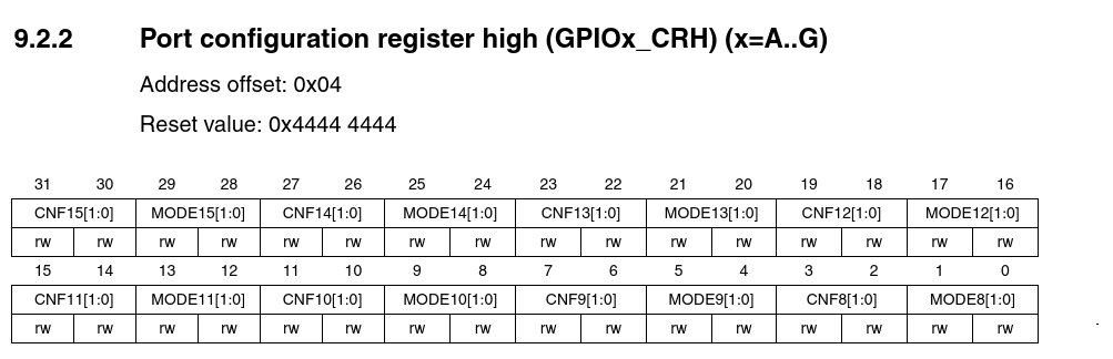
Where is BIT 13 ?
Look in the Reference Manual PDF, page 167 for “Port configuration register high (GPIOx_CRH)” and you will see that
MODE13[1:0] are BITS 20 and 21
CNF13[1:0] are BITS 22 and 23.
As before, we find that all the BITS are in the RESET DEFAULT of INPUT, FLOATING, including PC13.
GPIOC_CRH.

GPIOC_CRH.
GPIOC_CRH (read-write) $44444444
3|3|2|2|2|2|2|2|2|2|2|2|1|1|1|1|1|1|1|1|1|1|
1|0|9|8|7|6|5|4|3|2|1|0|9|8|7|6|5|4|3|2|1|0|9|8|7|6|5|4|3|2|1|0
0 1 0 0 0 1 0 0 0 1 0 0 0 1 0 0 0 1 0 0 0 1 0 0 0 1 0 0 0 1 0 0
ok.
Open bitfields.fs in your editor and search for “GPIOC_CRH” then look for “13” and you should see these lines, which control the Bitfields for MODE13 and CNF13. Just take note of these Words, don’t enter or run them. They are for your information only and have been previously loaded with “bluepill.support.fs”
: GPIOC_CRH_MODE13   ( %XX -- ) 20 lshift GPIOC_CRH bis! ;  \ GPIOC_CRH_MODE13   Port n.13 mode bits
: GPIOC_CRH_CNF13    ( %XX -- ) 22 lshift GPIOC_CRH bis! ;  \ GPIOC_CRH_CNF13    Port n.13 configuration  bits
These templates will be modified to configure PC-13 as a OUTPUT.
Firstly don’t assume MODE13[1:0] and CNF13[1:0] are in the default modes, we need to make this work under any pre-existing configurations.
Note
This solution is one of a infinitely variable set of solutions, it’s not the best or the most efficient.
PC-13 Output Word
Just take note of these Words, don’t enter or run them. They are for your information only and have been previously loaded with “bluepill.support.fs”
: GPIOC_13_clear ( -- )         \ Clear all GPIOC_13 config bits
  %11 20 lshift GPIOC_CRH bic!  \ GPIOC_CRH_MODE13  0,0
  %11 22 lshift GPIOC_CRH bic!  \ GPIOC_CRH_CNF13   0,0
;

: GPIOC_13_output ( -- )        \ Output, Push-Pull: MODE13:1,0   CNF13:0,0
  GPIOC_13_clear                \ MODE13:0.0  CNF13:0,0
  %10 20 lshift GPIOC_CRH bis!  \ MODE13:1,0
;
PC-13 Control Words
Just take note of these Words, don’t enter or run them. They are for your information only and have been previously loaded with “bluepill.support.fs”.
: pc13.high ( -- ) GPIOC_BSRR_BS13 ;
: pc13.low  ( -- ) GPIOC_BSRR_BR13 ;

: GPIOC_13_output ( -- )        \ Output, Push-Pull: MODE13:1,0   CNF13:0,0
   GPIOC_13_clear               \ MODE13:0.0  CNF13:0,0
   %10 20 lshift GPIOC_CRH bis! \ MODE13:1,0  SET PC13 as PUSH-PULL
   pc13.high                    \ Start with LED off
;

: ledon pc13.low ;   \ The Blue Pill obviously has the LED anode connected to +3.3v and the Cathode to PC13
                     \ (plus a resistor somewhere). When PC13 is HIGH the LED is OFF.
                     \ This means PC13 could be in "open collector mode" instead of "push-pull"and work fine also.
: ledoff pc13.high ;
LED On and Off
This Word configures PC-13 as a output, so type it into your terminal and hit enter.
GPIOC_13_output
Now type the following Words into your terminal, one at a time and hit enter. The LED should turn ON or OFF as instructed.
ledon

ledoff
The End
Congratulations, you have finished the Blue Pill Starter Kit !
Exercise for the reader
GPIOC_13_output is used to configure GPIOC_13 as a “PUSH-PULL” output, however this is the wrong MODE to use because the Blue Pill wiring expects a “OPEN-DRAIN”, can you change the code in “bluepill.support.fs” so that Open Drain is used instead ?
Don’t forget to verify that OPEN_DRAIN is actually in use by reading the GPIOC_CRH Register.
See some user contributed EXAMPLE CODE ?
What’s Next ?
That’s a BIG question!
If you want to keep using the Blue Pill then that 1096 page Technical Reference is waiting to be read, allow at least 5 years to become somewhat conversant with this 12 year old chip!
Perhaps you may like to consider other more modern STM32 chips instead, available as brand new STM Discovery or Nucleo boards for around $20 with integrated debugger/programmer ?
Chip |
Speed MHz |
On Board Peripherals |
Comments |
|---|---|---|---|
STM32L072 |
32 |
45 |
Low power Cortex-M0+ |
STM32F777 |
200 |
93 |
FAST and comprehensive |
If you want to continue with Forth you could look at the Next Steps page ?
Starter Kit Testing
All Starter Kit Words and the LED were tested on a LC Mini which has the same STM32F103 chip as the Blue Pill.
