blink-greenpill README
Project: blink-greenpill
Created: Thu  4 Feb 2021 22:39:18 AEDT
Author 2021 by t.j.porter <terry@tjporter.com.au>
Purpose: STM32F0 Assembly language tutorial
GDB-TUI
MCU: STM32F051
Board: "greenpill"
Core:
Required: arm-none-eabi, unix,
Recommended: Black Magic Probe and a "greenpill" (minimal STM32F0)
Black Magic Probe: https://mecrisp-stellaris-folkdoc.sourceforge.io/bluepill-bmp.html#bluepill-bmp
https://mecrisp-stellaris-folkdoc.sourceforge.io/stm32-boards.html?highlight=green#why-not-make-your-own-green-pill
Based on: -
Literature: -
blink-greenpill URL:
License: MIT, please see COPYING
Intended audience: basic STM32 register familarity, at least with RCC and GPIOB
Download Zipfile with all files including PDF’s: https://sourceforge.net/projects/mecrisp-stellaris-folkdoc/files/blink-greenpill-19.03.21-F1d92.zip
This is the golden era of embedded electronics
Today’s MCU’s are incredibly powerful and cheap. In 2016 I purchased a 32 pin, QFN, STM32F051. 32 bit MCU, with 8KB ram, 64kb flash and thirty two internal peripherals for $0.56 USD . In 1976 the Motorola 6800, 1MHz, 8 bit cpu with no peripherals, ram, clock or anything cost $170 USD each!
There are no shortage of free programming languages for ARM Cortex-M Microcontrollers in 2021, which is a far cry from the 1980’s when anything embedded was very, very expensive. Today we literally have too many choices to list with the most common being C, other popular languages are MicroPython, Rust, Lua, Forth etc.
But what about the first ever HLL embedded programming language known as “Assembly” ?
Why isn’t Assembly Programming more popular, is it because Assembly is hard, complicated or non productive ?
One thing we do know is that Assembly is not slow, it is potentially the fastest programming language available.
Assembly Code
Assembly coding can be very easy with the right development tools, or frustratingly difficult without them. Frustrating because basic assembly coding provides zero developer feedback and the simplest of errors such as a typo will normally render the device utterly unresponsive.
First the “hard to read version” is shown. This lacks useful names for registers and the technical manual must be consulted at every step to decode the purpose.
Then the alternate “easy to maintain” version is shown and the advantages explained in detail.
The traditional ‘Blinky’ is used as the example, but this one only blinks when portb-8 is low. The total size of the compiled binary is 120 bytes.
The Blinky example runs on actual target hardware via a BlackMagicProbe on a Bluepill using GDB and arm-none-eabi on a PC.
Blink.s Source Code
This is the hard to read and maintain version. One couldn’t be blamed for running away screaming after reading it.
.cpu cortex-m0
.thumb
.include "../svd2forth/gpio-equates.s"
.include "../svd2forth/bitposn-equates.s"
.include "../svd2forth/STM32F051.equates.s"
.syntax unified
.global main
Vector_Table: .word 0x20000000
ResetVector:  .word main + 1
.text

main:   ldr  r0, = 0x40021014
        ldr  r1, [r0]
        ldr  r2, = 0x4000
        orrs r2, r1
        str  r2, [r0]

moder:  ldr  r0, = 0x48000400
        ldr  r1, [r0]
        ldr  r2, = 0x4000
        orrs r2, r1
        str  r2, [r0]

pullx:  ldr  r0, = 0x4800040C
        ldr  r1, [r0]
        ldr  r2, = 0x24000
        orrs r2, r1
        str  r2, [r0]

check_pb8: @ if PB-8 = LOW then LOOP until PB-8 = HIGH then blink
        ldr  r0, = 0x48000410
        ldr  r1, [r0]
        ldr  r2, = 0x100
        tst  r1, r2
        bne  check_pb8

on_off: ldr r1, = 0x48000418
r4_on:  ldr r4, = 0x80
r5_off: ldr r5, = 0x800000

led_on: str r4, [r1]
        bl delay

led_off:str r5, [r1]
        bl delay
        b check_pb8

 delay: @ r4 = 0x80 shifted left 13 times = 0x100000, delay about 1 second @ 8MHz cloc
        lsls r0,r4, #13
 loop:  subs r0,r0, #1
        bne loop
 end:   bx lr
Blink.s Source Code
This is the easy to read and maintain version. It uses CMSIS-SVD syntax for easy reference with the STM32F051 Technical Manual and is well commented. When used with decent equates file(s) and GDB, it’s incredibly easy to write and debug embedded code.
Of course you must also know your hardware intimately which is a given for embedded design.
.cpu cortex-m0                              @ Tell the assembler what model of Cortex-M this is for
.thumb                                      @ Cortex micros only understand thumb(1) code
.include "../svd2forth/gpio-equates.s"      @ GPIO configurations such as "INPUT" or "OUTPUT"
.include "../svd2forth/bitposn-equates.s"   @ BIT0 = 0x00000001, BIT3 = 0x00000008, BIT31 = 0x80000000
.include "../svd2forth/STM32F051.equates.s" @ Every register and bitfield equate for the MCU (from Svd2Forth)
.syntax unified                             @ Use a modern syntax for Arm THUMB instructions.
.global main                                @ Makes the symbol visible to ld
Vector_Table: .word 0x20000000              @ Stack pointer value when stack is empty
ResetVector:  .word main + 1                @ Mandatory that the LSB = 1
.text                                       @ what follows is code

main:   ldr  r0, = RCC_AHBENR               @ AHB Peripheral Clock enable register = 0x40021014
        ldr  r1, [r0]                       @ save existing contents of AHB Peripheral Clock enable register in r1
        ldr  r2, = RCC_AHBENR_iopben        @ I/O port B clock enable = 0x40000
        orrs r2, r1                         @ Orrs with previous contents of AHB Peripheral Clock enable register
        str  r2, [r0]                       @ save back to AHB Peripheral Clock enable register, any previous set bits are untouched

moder:  ldr  r0, = GPIOB_MODER              @ GPIOB port mode register = 0x48000400
        ldr  r1, [r0]
        ldr  r2, = (INPUT << GPIOB_MODER_MODER8) + (OUTPUT << GPIOB_MODER_MODER7)  @ Set PB-8 to INPUT, PB-7 to OUTPUT.
        orrs r2, r1
        str  r2, [r0]

pullx:  ldr  r0, = GPIOB_PUPDR              @ GPIOB_PUPDR register = 0x4800040C
        ldr  r1, [r0]
        ldr  r2, = (PULL_DOWN << GPIOB_PUPDR_PUPDR8) + (PULL_UP << GPIOB_PUPDR_PUPDR7)   @ PB-8 has a pull down, PB-7 has a pull up
        orrs r2, r1
        str  r2, [r0]

check_pb8:                                  @ if PB-8 = LOW then LOOP until PB-8 = HIGH then blink
        ldr  r0, = GPIOB_IDR
        ldr  r1, [r0]                       @ read the PB input data register
        ldr  r2, = GPIOB_IDR_idr8           @ load r2 with the idr8 mask
        tst  r1, r2                         @ performs a bitwise AND operation on the value in r1 and r2, update condition codes
        bne  check_pb8

on_off: ldr r1, = GPIOB_BSRR                @ GPIOB bit set/reset register (address = 0x48000418)
r4_on:  ldr r4, = GPIOB_BSRR_bs7            @ PB-7 on = 0x80
r5_off: ldr r5, = GPIOB_BSRR_br7            @ PB-7 off = 0x800000

led_on: str r4, [r1]
        bl delay

led_off:str r5, [r1]
        bl delay
        b check_pb8

 delay: lsls r0,r4, #13                     @ r4 = 0x80 shifted left 13 times = 0x100000, delay about 1 second @ 8MHz clock
 loop:  subs r0,r0, #1
        bne loop
 end:   bx lr                               @ return to caller
Assembler Directives Explained
This is the block of code above “main:” and it tells the assembler how to compile the source below it.
.cpu cortex-m0
Tell the assembler what model of Cortex-M this is for
.thumb
Cortex micros only understand thumb code. M0 only understands Thumb1, Cortex-M3 and above can use Thumb1 or Thumb2.
.include “gpio-equates.s”
GPIO configurations such as “INPUT” or “OUTPUT”
.include “bitposn-equates.s”
BIT0 = 0x00000001, BIT3 = 0x00000008, BIT31 = 0x80000000
.include “STM32F0xx-tp1.svd.equates.s”
Every register and bitfield equate for the MCU (from Svd2Forth)
.syntax unified
Two slightly different syntaxes are support for ARM and THUMB instructions. The default, divided, uses the old style where ARM and THUMB instructions had their own, separate syntaxes. The new, unified syntax, which can be selected via the .syntax directive, and has the following main features:
Immediate operands do not require a # prefix.
The IT instruction may appear, and if it does it is validated against subsequent conditional affixes. In ARM mode it does not generate machine code, in THUMB mode it does.
For THUMB instructions conditional affixes can be used, but only inside the scope of an IT instruction.
All of the instructions new to the V6T2 architecture (and later) are available. (Only a few such instructions can be written in the divided syntax).
The .N and .W suffixes are recognized and honored.
All instructions set the flags if and only if they have an s affix.
.global main
Makes the symbol visible to the loader (ld) for more information in the listings.
Vector_Table: .word 0x20000000
Stack pointer value when stack is empty
ResetVector: .word main OR 1
Vectors are the address with the lsbit set.
.text
Now the actual source code is listed.
Registers
The Cortex-M documentation is vast, and there are a LOT of Registers involved. Can you imagine the work involved in manually creating the .EQU statements for Registers and Bitfields ?
Some statistics for various Cortex-M MCU’s.
MCU |
Peripherals |
Registers |
Register Bitfields |
|---|---|---|---|
STM32F0xx |
37 |
413 |
3044 |
STM32F303x |
38 |
549 |
3857 |
STM32F103xx |
53 |
722 |
4833 |
TM4C129x |
65 |
2137 |
7347 |
STM32F7x |
89 |
1737 |
14091 |
STM32F7x7 |
93 |
2093 |
17051 |
CMIS-SVD
ARM created CMSIS-SVD to automate the job of telling the industry ‘standard’ C programs about Cortex-M Peripherals, Registers and Register Bitfields with SVDConv.exe, however that is of no use Assembly code writers so Svd2forth (and others) were developed, initially based on work by Ralph Doering as cmsis-svd-fth (https://github.com/ralfdoering/cmsis-svd-fth).
Because the assembler takes any sized .equ file as an include, the entire gpio-equates.s may be used, or even the MUCH larger ones for MCU’s like the STM32H7xx. The Assembler will just take what it needs from them and they won’t bulk up your binary program at all.
Cortex-M Registers and Bitfields
Register: These are the areas used by every peripheral in the MCU. All embedded code uses these registers for configuration or data.
Bitfield: Most of the registers are divided up into smaller sections and these are known as Bitfields.
To make a peripheral do our bidding involves configuring Bitfields to one of the vast array of choices as outlined in the ../pdfs/stm32f0x-reference_manual.pdf.
Workflow using the Equates files
In this case src/STM32F051.equates.s
Two code sections taken from this project are enough to illustrate the choices.
Code Section 1: Literals
main:  ldr  r0, = RCC_AHBENR               @ AHB Peripheral Clock enable register = 0x40021014
       ldr  r1, [r0]                       @ save existing contents of AHB Peripheral Clock enable register in r1
       ldr  r2, = RCC_AHBENR_IOPBEN        @ I/O port B clock enable = 0x40000
       orrs r2, r1                         @ Orrs with previous contents of AHB Peripheral Clock enable register
       str  r2, [r0]                       @ save back to AHB Peripheral Clock enable register, any previous set bits are untouched
Literal
This is any item represented in ALL CAPS, such as RCC_AHBENR or RCC_AHBENR_IOPBEN. These are complete and can be loaded into a register as is, i.e. “ldr r0, = RCC_AHBENR” or “ldr r2, = RCC_AHBENR_IOPBEN”
.equ Examples
.equ RCC_AHBENR, RCC_BASE + 0x14 @ ([read-write] reset = 0x00000014) AHB Peripheral Clock enable register
.equ RCC_AHBENR_IOPBEN, 1 << 18   @ I/O port B clock enable
RCC_AHBENR equals the value 0x40021014 and RCC_AHBENR_IOPBEN equals 1 shifted 18 places to the left which is 0x40000
Shifter
This is any item where the Bitfield name is in lower case, which means it is meant to be used to SHIFT a literal to the left X places.
In the example below X = 16 for GPIOB_MODER_moder8 and 14 for GPIOB_MODER_moder7
.equ Examples
.equ GPIOB_MODER_moder8, 16   @ Shifted literal = 2
.equ GPIOB_MODER_moder7, 14   @ Shifted literal = 2
The values specified in these equates are the number of left shifts performed to form a literal. The shifted literal can be anything, but a self explanatory label will make your source much easier to read and maintain.
The shifted literal is the exact number of bits to be used with the Shifter. Any other bitwidth is prohibited.
Both GPIOB_MODER_moder8 and GPIOB_MODER_moder7 need shifted literals equal to 2 bits. Shifted literals can be any other value of bits as seen in in the svd2forth/STM32F051.equates.s file.
These are further explained in the next example “Bitfields with more than one bit”.
Code Section 2: Bitfields with more than one bit
moder:  ldr  r0, = GPIOB_MODER  @ GPIOB port mode register = 0x48000400
        ldr  r1, [r0]
        ldr  r2, = (INPUT << GPIOB_MODER_moder8) + (OUTPUT << GPIOB_MODER_moder7)  @ Set PB-8 to INPUT, PB-7 to OUTPUT.
        orrs r2, r1
        str  r2, [r0]
GPIOB_MODER_moder8 is expecting a shifted literal of two bits (Width:2) and “INPUT” is supplied. The Value of “INPUT” equals 0b00 as can be found in svd2forth/gpio-equates.s file. .. code-block:: none
.equ INPUT, 0b00
0b00 shifted 16 places to the left = 0x00. It could have been omitted as the default value of all bitfields in GPIOB_MODER is 0x00000000 as shown in svd2forth/gpio-equates.s It’s used for purpose of example only.
GPIOB_MODER_moder7 is expecting a shifted literal of two bits and “OUTPUT” is supplies. The Value of “OUTPUT” = 0b01 as can be found in svd2forth/gpio-equates.s .. code-block:: none
.equ OUTPUT,0b01
0b01 shifted 16 places to the left = 0x00010000 or 0b10000000000000000
Therefore (INPUT << GPIOB_MODER_moder8) + (OUTPUT << GPIOB_MODER_moder7) = 0 + 0x00010000, which is 0x00010000.
Summary
By using the CMSIS-SVD syntax in the source all the “magic numbers” are automatically compiled into the binary resulting in maintainable source and removing the human error of trying to hand type hex values from the technical manual.
Consistent Naming
Take “RCC_AHBENR” for instance, I know I need it because pdfs/stm32f0x-reference_manual.pdf lists it in section 6.4.6 “ AHB peripheral clock enable register (RCC_AHBENR)” on page 120. Here I can see that to enable GPIOB I need to set the Bitfield “IOPBEN”.
I can type or paste the register and bitfield name directly from the pdfs/stm32f0x-reference_manual.pdf as is. This is the beauty of using a consistent naming strategy such as CMSIS-SVD. It also makes your assembly code portable to others using the same strategy.
This is exactly what I did when writing Code Section 1. above
The Assembler knows all about “RCC_AHBENR” as it’s specified in the header (.include “../svd2forth/STM32F051.equates.s”) so all you have to do is type it into the source and when you type “make” it will be found and assembled.
The same is true of the Bitfield “IOPBEN”.
If there is a error, the Assembler will tell you about it.
Tying everything together
Recommended: Black Magic Probe and a “greenpill” (minimal STM32F0)
Once the Hardware is connected:
Project Hardware
A Black Magic Probe and a simple STM32F051 board are used as shown below. If you want to use another model of STM32 you can create an equates file for it using the latest SVD2FORTH at: https://sourceforge.net/projects/mecrisp-stellaris-folkdoc/files/svd2forth-v3-stm32-20.03.21-F7a01.zip
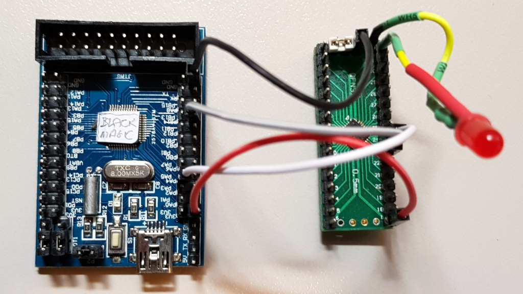
Connections
STM32F103 BMP Board |
Functions |
STM32F051 pins |
Wire Colors I used |
|---|---|---|---|
Gnd |
GND |
Centre |
black |
PA-5 |
SWCLK |
24 |
white |
PB-14 |
SWDIO |
23 |
grey |
3.3V (source) |
3.3V |
1,5,7 |
red |
PB-1 |
NRESET LED Anode LED Cathode |
4 32 Centre |
brown yellow/red yellow/black |
Running the Source
Once the source has been created it needs to be tested, preferably on this hardware and this is the next step.
type “cd src/” from the root release directory
type “make clean” then type “make”
either type make gdb or run the file “run-gdbtui.sh”, the result is the same
A window should then pop up looking something like this.
GDB
GDB is used to single step through the source code, blink the led etc. It runs on the actual MCU in the simple STM32F051 board.
Register values can be seen and memory locations can be printed.
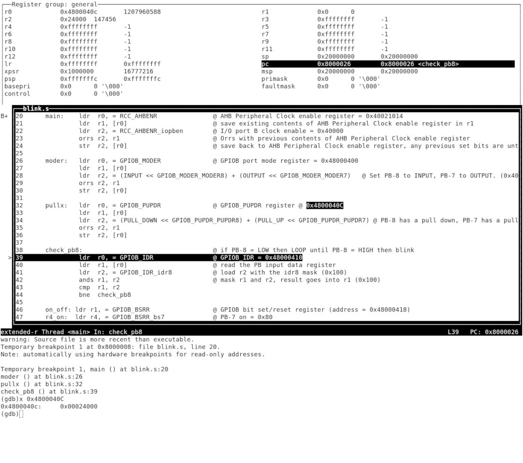
Basic GDB Use
Once the GDB screen pops up, press “enter”
Enter “s” (at the GDB command line) for single step and watch the cursor move one step at a time thru the source code. Pressing ‘enter’ will repeat the last command so one doesn’t need to keep pressing “s”.
When you get to the following line of code and press enter, the LED will light on the board (providing PB-8 is LOW).
led_on: str r4, [r1]
Entering “run” will make the LED blink (providing PB-8 is LOW) until <ctrl>c is entered to stop it running.
This is a simple demo and GDB is far more advanced than this, enter “help” at the GDB command line to see what I mean.
Editors
Svd2forth/STM32F051.equates.s can be searched as it includes the description field for every item, items such as “RCC_AHBENR” can be copied and pasted into the source.
Advanced Editors
Open buffers can be searched from the source file and selected text inserted. This means the writer does not need to leave the source file while coding.
In VIM the cursor is positioned after the “_” in the code below and then “<ctrl>xl” is entered which results in the following pop-up window.
.equ RCC_
Picture: Vim Buffer Search Pop Up
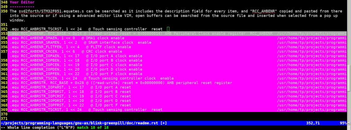
Wherever the highlighted bar is positioned in the pop-up window, pressing enter inserts that line as shown below.
Picture: Vim Buffer Selection

Macros
There is far more to Assembly language, for instance “macros” offer great time savings and programmability. To read about macros see PDF: http://www.mcs.sdsmt.edu/lpyeatt/courses/314/Chapter_02.pdf and my followup article to this one.
Conclusion
I hope this article has been useful and easy to understand, if not please leave a message at https://sourceforge.net/p/mecrisp-stellaris-folkdoc/discussion/general/thread/2a381d76ef/
PDF’s
Included with this release in the ../pdfs directory are the following documents which I used when making this article.
Note
This document doesn’t touch on areas such as “special functions” or ARM specific parts such as “Systick” so this documentation is not included.
Filename |
Description |
|---|---|
BlackMagicProbe.pdf |
How to get the best from a BlackMagicProbe |
PM0215-programming-manual.pdf |
The STM32 Cortex-M0 instruction set as used here starting at page 31. |
GNU_Assembler.pdf |
Using the GNU assembler used in this tutorial |
stm32f0x-reference_manual.pdf |
All the ST peripheral information you need. Search this for registers such as “GPIOB_MODER” |
arm-v6-m-architecture-reference.pdf |
Deep dive into arm-v6-m, bedtime reading |
Useful References
ARM-ASM-Tutorial
By Niklas Gürtler. This is a fantastic Assembly tutorial written for the ARMv7-M, Cortex-M3 STM32F103 MCU which is a lot more advanced than the Cortex-M0 I’m using in this tutorial, but all the important parts of the process such as the Linker usage are the same.
Useful-GDB-commands
https://github.com/blacksphere/blackmagic/wiki/Useful-GDB-commands
