Quadrature Rotary Switch
Not that long ago, ‘rotary switches’ consisted of banks of wafers and contacts, they could be small with only one wafer and a couple of contacts or huge, long, gold plated and expensive. Of course they are still available today and have their specialised uses.
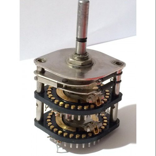
23 Position Wafer Rotary Switch
This rotary switch has 23 positions and two wafers. Each wafer has one ‘wiper’ that makes contact with a terminal at each position.
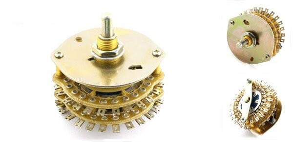
Hi Quality Rotary Switch
We won’t see many of these again, they are definitely a thing of the past, with chrome or silver plated brass body, gold plated high current contacts etc.
Rotary Encoder
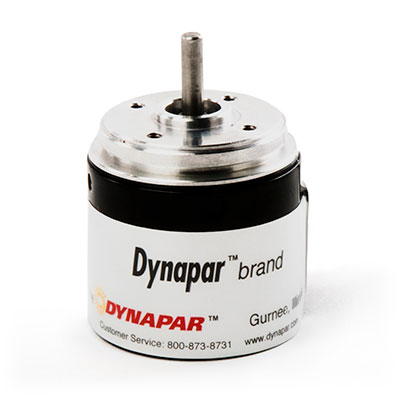
This is a high quality optical quadrature rotary position encoder, it’s designed for CNC positioning, usually with a servo motor and not discussed in this article.
Quadrature Rotary Switch
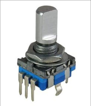
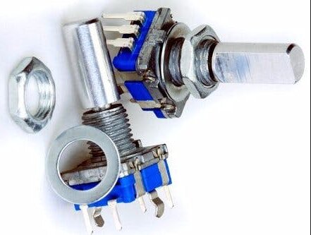
This is the article subject, the ‘Quadrature Rotary Switch’.
These can be very small, cheap and simple and yet just as useful or even more useful as the old “wafer type’ when deployed in embedded designs.
They can replace the wafers and wires with their attendant losses and interference while decrease manufacturing costs enormously. They can drive IGBJT’s from a MCU and control hundreds of amps, or high speed FET switches capable of GHz frequencies.
The majority are a mechanical only design where the high end ones are optical and last forever, with no switch ‘bounce’, these cost $25 and up.
These switches can be as cheap as AUD $0.20 each, search for ‘rotary switch quadrature’ at https://www.arrow.com/ my favorite supplier.
The pictured units above are the mechanical type and the exact unit used in this article which also features a N/O PB switch as well as the encoder. To activate the switch, the shaft of the encoder is pressed. This shows the two pins for the pb switch and three pins for the encoder.
This unit has twenty ‘detents’ which hold the shaft in positions 1 - 20, and these can be felt as the switch is rotated.
Complexity
There is a price to pay for all the Quadrature Rotary Switch advantages above, the switch can’t just be wired up like a Wafer Rotary Switch and used right away because the switch positions have to be ‘decoded’ first by a specialised chip or a microprocessor and that’s what I’m doing next using a STMicro STM32F0 Discovery board and ‘quadrature decoding’.
The aim of this article is to demonstrate how this can be done using a STM32F051 MCU and Mecrisp-Stellaris Forth.
What is ‘QUADRATURE DECODING’ ?
There are a million articles online, here is a summary.
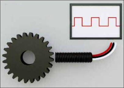
Single Channel Encoder
This is a single channel (non quadrature) encoder and can measure the speed of a shaft but not the absolute position or direction of rotation.
Dual Channel Encoder
Quadrature Type
Using two code tracks with sectors positioned 90 degree out of phase, the two output channels of the quadrature encoder indicate both position and direction of rotation. For example, if A leads B, the disk is rotating in a clockwise direction. If B leads A, the disk is rotating in a counter-clockwise direction. Therefore, by monitoring both the number of pulses and the relative phase of signals A and B, the microcontroller can track both the position and direction of rotation.
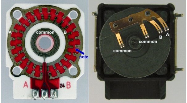
Mechanical Rotary Switch Type; cheap and nasty, but the design of Grey Code decoding makes for a surprisingly reliable switch.
Grey Code
Grey Code is used in Quadrature Encoders because of its ability to handle noise, this link has a good explanation: https://www.tutorialspoint.com/what-is-gray-code
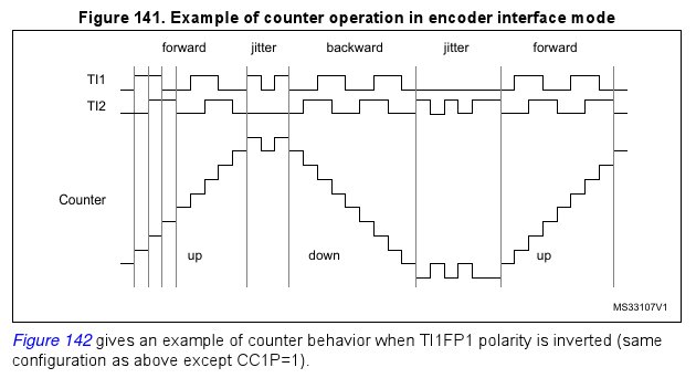
STmicro Example
Technical Manual RM0091, Figure 141. Example of counter operation in encoder interface mode. Page 424/1004. The manual gives extensive information on quadrature decoding along with example C code.
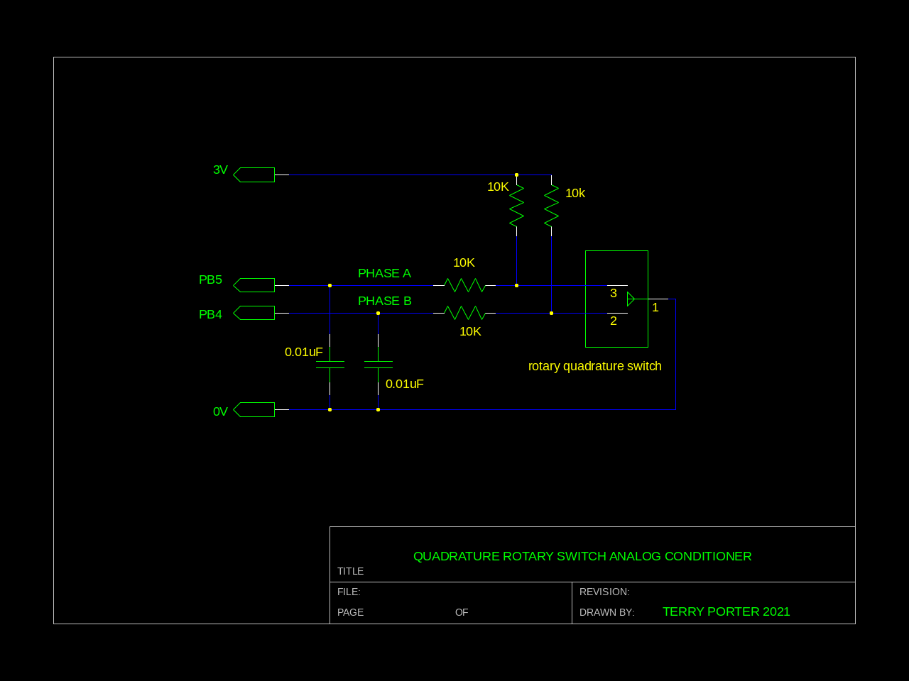
Schematic
Contact Bounce
Because mechanical encoders have a lot of contact bounce I find ‘conditioning’ the signal channels as below reduces false counts. Omitting these parts and just using the MCU internal 30K GPIO pullups can be problematic if you run long unshielded wires to the encoder because they can easily pick up noise, mains hum etc.
This ‘conditioning’ gives a nice clean signal right ?
… not so much, see ‘conditioner waveforms’ below.
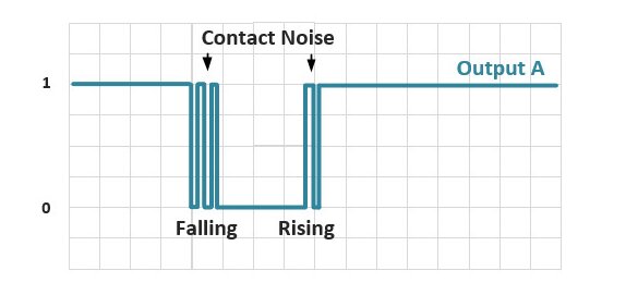
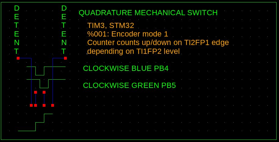
Switch Waveforms
Here is a picture of the (conditioned) switch phases as the switch is slowly rotated between detents.
Oscilloscope channel-2 shows one contact (phase), and oscilloscope channel-1 the other.
test-switch
A “test-switch” Word included in the source visually shows the switch contacts state in operation using the STM32F0 Discovery Board leds. The position of the switch and the state of the leds is the same as the ‘Switch Waveform’.
run “test-switch”
While the switch is located at a detent the Green and BLUE leds will turn on.
Turn Switch slowly clockwise until the BLUE led turns off
Continue turning until the GREEN led turns off. Both leds are now off.
Continue until the BLUE led turns back on
Continue until the GREEN led turns back on. Both leds are now on and the switch has reached the next detent.
This picture shows the detent positions and idealised voltages as the switch is turned clockwise.
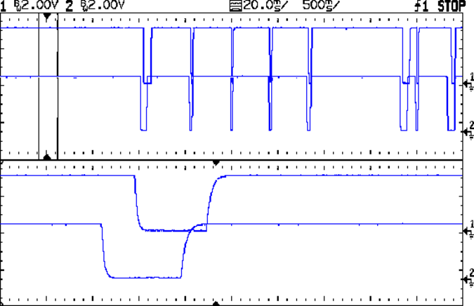
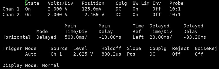
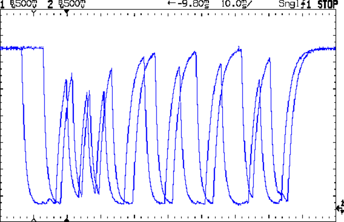
Conditioner Waveforms
The analog ‘conditioner’ forms a ‘low pass filter’ which attenuates all higher frequency signals including switch debounce spikes and fast shaft rotation signals. The faster the shaft is turned the smaller the signals until they’re unusable. By design of the RC filter, this only occurs at speeds above normal use.
Taken at PB4 and PB5 (Phase B and Phase A) as I flicked the knob as fast as I possibly could. You can see the initial acceleration causing loss of voltage excursion, which recovers as it slows down. This is the worst case signal scenario which occurs at higher than normal rotational speeds. This waveform is contrived because it is much slower in real world use.
Decoding
What is incredible is that the switch decoding was perfect, no missed steps.
d
0
1 CW
2 CW
3 CW
4 CW
5 CW
6 CW
7 CW
8 CW
How does it work ?
STM32Fxx timers 1,2 and 3 have a ‘quadrature encoder’ mode (amongst many others). Timer3 in this mode is used to decode the switch phases A and B via Ports PB4 and PB5. A main loop checks the position of the switch and if it changes, the new position is printed. No interrupts or DMA are used.
As mentioned previously, there is also a test program to visually show the switch contacts (via the F0 Disco Board leds) in relation to the detents as the switch shaft is rotated.
Sourcecode
This source was made using my (still Alpha level) SVD2FORTH-V6. If you haven’t read my Bitfields article before I recommend reading it before proceeding.
\ ------------------------------------------------------------------------------ \
\ sys.fs
\ purpose: set up system utilities
\ Not preprocessed.

compiletoram

   init.calltrace	   \ Prevent "Unhandled Interrupt ..." and list the problem instead.
   48mhz		   \ Increase MCU clock to 48 MHz
   48000 init.systick	   \ Set the Systick to 1ms increments

\ ------------------------------------------------------------------------------ \
\ includes.fs
\ f0-quadrot-sw2.fs preprocessor generated dependencies
compiletoram
$40000400 constant TIM3_CR1 \ control register 1
$40000408 constant TIM3_SMCR \ slave mode control register
$40000418 constant TIM3_CCMR1_Input \ capture/compare mode register 1 input  mode
$40000420 constant TIM3_CCER \ capture/compare enable  register
$40000424 constant TIM3_CNT \ counter
$4000042C constant TIM3_ARR \ auto-reload register
$40021014 constant RCC_AHBENR \ AHB Peripheral Clock enable register  RCC_AHBENR
$4002101C constant RCC_APB1ENR \ APB1 peripheral clock enable register  RCC_APB1ENR
$48000400 constant GPIOB_MODER \ GPIO port mode register
$48000410 constant GPIOB_IDR \ GPIO port input data register
$48000420 constant GPIOB_AFRL \ GPIO alternate function low  register
$48000800 constant GPIOC_MODER \ GPIO port mode register
$48000818 constant GPIOC_BSRR \ GPIO port bit set/reset  register
: GPIOB_AFRL_AFRL4<<   ( %4 --  x )   16 lshift   ; \ rw","4","16","Alternate function selection for port x  bit y y = 0..7
: GPIOB_AFRL_AFRL5<<   ( %4 --  x )   20 lshift   ; \ rw","4","20","Alternate function selection for port x  bit y y = 0..7
: GPIOB_IDR_IDR4?    ( -- 1|0 )   1 4 lshift GPIOB_IDR bit@   ; \ ro","1","4","Port input data y =  0..15
: GPIOB_IDR_IDR5?    ( -- 1|0 )   1 5 lshift GPIOB_IDR bit@   ; \ ro","1","5","Port input data y =  0..15
: GPIOB_MODER_MODER4<<   ( %2 --  x )   8 lshift   ; \ rw","2","8","Port x configuration bits y =  0..15
: GPIOB_MODER_MODER5<<   ( %2 --  x )   10 lshift   ; \ rw","2","10","Port x configuration bits y =  0..15
: GPIOC_BSRR_BR8!    ( --  )   1 24 lshift GPIOC_BSRR !   ; \ wo","1","24","Port x reset bit y y =  0..15
: GPIOC_BSRR_BR9!    ( --  )   1 25 lshift GPIOC_BSRR !   ; \ wo","1","25","Port x reset bit y y =  0..15
: GPIOC_BSRR_BS8!    ( --  )   1 8 lshift GPIOC_BSRR !   ; \ wo","1","8","Port x set bit y y=  0..15
: GPIOC_BSRR_BS9!    ( --  )   1 9 lshift GPIOC_BSRR !   ; \ wo","1","9","Port x set bit y y=  0..15
: GPIOC_MODER_MODER8<<   ( %2 --  x )   16 lshift   ; \ rw","2","16","Port x configuration bits y =  0..15
: GPIOC_MODER_MODER9<<   ( %2 --  x )   18 lshift   ; \ rw","2","18","Port x configuration bits y =  0..15
: RCC_AHBENR_IOPAEN    ( --  x )   1 17 lshift   ; \ rw","1","17","I/O port A clock enable
: RCC_AHBENR_IOPBEN    ( --  x )   1 18 lshift   ; \ rw","1","18","I/O port B clock enable
: RCC_AHBENR_IOPCEN    ( --  x )   1 19 lshift   ; \ rw","1","19","I/O port C clock enable
: RCC_APB1ENR_TIM3EN    ( --  x )   1 1 lshift   ; \ rw","1","1","Timer 3 clock enable
: TIM3_ARR_ARR_L<<   ( %16 --  x )      ; \ rw","16","0","Low Auto-reload value
: TIM3_CCER_CC1P    ( --  x )   1 1 lshift   ; \ rw","1","1","Capture/Compare 1 output  Polarity
: TIM3_CCER_CC2P    ( --  x )   1 5 lshift   ; \ rw","1","5","Capture/Compare 2 output  Polarity
: TIM3_CCMR1_Input_CC1S<<   ( %2 --  x )      ; \ rw","2","0","Capture/Compare 1  selection
: TIM3_CCMR1_Input_CC2S<<   ( %2 --  x )   8 lshift   ; \ rw","2","8","Capture/compare 2  selection
: TIM3_CCMR1_Input_IC1F<<   ( %4 --  x )   4 lshift   ; \ rw","4","4","Input capture 1 filter
: TIM3_CCMR1_Input_IC2F<<   ( %4 --  x )   12 lshift   ; \ rw","4","12","Input capture 2 filter
: TIM3_CR1_CEN    ( --  1 )   1   ; \ rw","1","0","Counter enable
: TIM3_CR1_DIR    ( --  x )   1 4 lshift   ; \ rw","1","4","Direction
: TIM3_SMCR_SMS<<   ( %3 --  x )      ; \ rw","3","0","Slave mode selection

\ ------------------------------------------------------------------------------ \
\ gpio.fs
\ purpose: gpio configs
\ Inputs:
\  PB4, TIM3_CH1, AF1 = 0001
\  PB5, TIM3_CH2, AF1 = 0001

: gpio-init ( -- )
RCC_AHBENR_IOPAEN	      \ Enable Ports A,B and C clocks
RCC_AHBENR_IOPBEN
RCC_AHBENR_IOPCEN
+ + RCC_AHBENR bis!

OUTPUT GPIOC_MODER_MODER9<<   \ PB9 is Blue LED
OUTPUT GPIOC_MODER_MODER8<<   \ PB8 is Green LED
+ GPIOC_MODER bis!
;

: greenon  ( -- ) GPIOC_BSRR_BS9! ;   \ green led on
: greenoff ( -- ) GPIOC_BSRR_BR9! ;   \ green led off
: blueon  ( -- ) GPIOC_BSRR_BS8! ;    \ blue led on
: blueoff ( -- ) GPIOC_BSRR_BR8! ;    \ blue led off

: pb4,5-tim3-config	      \ PB 4 and 5 configued for TIM3 inputs
AF GPIOB_MODER_MODER4<<	      \ PB4 and PB5 to use the two quadrature switch phaseA and phaseB
AF GPIOB_MODER_MODER5<<
+ GPIOB_MODER bis!
:

\ AF1: PB4 and PB5 --> TIM3
AF1 GPIOB_AFRL_AFRL4<<	      \ AF1 = PB4 --> TIM3_CH1
AF1 GPIOB_AFRL_AFRL5<<	      \ AF1 = PB5 --> TIM3_CH2
+ GPIOB_AFRL bis!
;

: test-switch-config ( -- )   \ Make PB4 and PB% inputs to test the encoder logic levels and sequences re detents.
   gpio-init
   %11 GPIOB_MODER_MODER4<<
   %11 GPIOB_MODER_MODER5<<
   + GPIOB_MODER BIC!	      \ clear the bits for INPUT MODE
;

: PB5?	 ( -- 0|1 )	      \ high = GREEN on
   GPIOB_IDR_IDR5? IF greenon ELSE greenoff THEN
;

: PB4?	 ( -- 0|1 )	      \ high = BLUE on
   GPIOB_IDR_IDR4? IF blueon ELSE blueoff THEN
;
\ ------------------------------------------------------------------------------ \
\ tim3.fs
\ purpose: config
\ Inputs:
\ PB4, TIM3_CH1, AF1 = %0001
\ PB5, TIM3_CH2, AF1 = %0001


: tim3-init ( -- )
   RCC_APB1ENR_TIM3EN RCC_APB1ENR bis!    \ Timer 3 clock enable
;

: tim3-config ( -- )
   \ Configure TI1FP1 on TI1 (CC1S = 01) and TI1FP2 on TI2 (CC2S = 01)
   \ This bit-field defines the direction of the channel (input/output) as well as the used input
   %01 TIM3_CCMR1_Input_CC1S<<	    \ Capture/Compare 1  selection %01: CC1 channel as INPUT, IC1 is mapped on TI1.
   %01 TIM3_CCMR1_Input_CC2S<<	    \ Capture/Compare 1  selection %01: CC2 channel as INPUT, IC2 is mapped on TI2
   + TIM3_CCMR1_Input hbis!

   \ Configure TI1FP1 and TI1FP2 to non inverted output.  (CC1P = CC2P = %0)
   TIM3_CCER_CC1P		    \ Capture/Compare 1 output polarity
   TIM3_CCER_CC2P		    \ Capture/Compare 2 output polarity
   + TIM3_CCER hbic!		    \ hbic! means the selected bit(s) will be cleared

   \ Configure Encoder mode 1 - Counter counts up/down on TI2FP1 edge depending on TI1FP2 level.
    %001 TIM3_SMCR_SMS<<	    \ %001: Encoder mode 1
    TIM3_SMCR hbis!

   \ Set ARR to 39. This the key! it should be 38 by my estimation but a extra 1 is required, why ?
    39 TIM3_ARR_ARR_L<<  TIM3_ARR ! \ works perfectly CCW thru 0 AND CW thru 0.

   \ Filter. Unscientific test; flicking the switch around seems more stable with %0011
    %0011 TIM3_CCMR1_Input_IC1F<<  \ %0011: fSAMPLING = fCK_INT, N = 8
    %0011 TIM3_CCMR1_Input_IC2F<<
    + TIM3_CCMR1_Input bis!

   \ (4) Enable the counter by writing CEN=1 in the TIMx_CR1 register
   TIM3_CR1_CEN  TIM3_CR1 hbis!	    \ TIM3 enable
;


\ ------------------------------------------------------------------------------ \
\ f0-quadrot-sw2.fs
\ purpose: Main program
\ Registers Used:
\ GPIOA, GPIOB, GPIOC, RCC, TIM3,
\ Note: TIM 1, 2 and 3 are capable of quadrature input.
\ Inputs:
\  PB4, TIM3_CH1, AF1 = 0001
\  PB5, TIM3_CH2, AF1 = 0001


0 variable oldcount
0 variable newcount

: detent? ( -- ) TIM3_CNT @ 2 / u.  ;  \ read the switch detent position

: dir? ( -- )
   oldcount @ -1 <> IF		       \ don't print direction if oldcount is fake startup value of -1
      TIM3_CR1_DIR TIM3_CR1 bit@ not   \ what direction is the switch moving, CW or CCW ?
      IF ." CW " ELSE ." CCW " THEN
   THEN
   cr
;

: poschange?			       \ Has the position changed ?
   newcount @ oldcount @ = IF	       \ no postition change
   ELSE				       \ switch position change, print position and direction
   detent? dir?
   newcount @ oldcount !
   THEN
;

: detents? ( -- ) cr
   -1 oldcount !		       \ -1 so that on powerup it displays detent = 0
   0 TIM3_CNT !			       \ zero the position counter
      BEGIN
      TIM3_CNT @ 2 / newcount !	       \ I get 2 counts per detent because all edges are being counted, but only want one count.
      poschange?
   key? UNTIL			       \ Escape main loop if any keyboard key is pressed
;


: test-switch   ( -- )	\ PB4 = BLUE. PB5 = GREEN.
   test-switch-config	\ Very slowly turn switch, watch led's to see contact and detent sequence.
   BEGIN
      PB4?		\ high = BLUE on
      PB5?		\ high = GREEN on
   key? UNTIL		\ Escape main loop if any keyboard key is pressed
;


: d ( -- )		\ print switch detent and direction, CCW or CW
   gpio-init
   tim3-init
   pb4,5-tim3-config
   tim3-config
   detents?
   cr
;

: t ( -- ) test-switch	\ rotate switch, leds will be ON for logic HIGH, off for logic LOW, PB4 = BLUE, PB5 = GREEN
;
Summary
A real world test of a cheap (AUD $1.50 ea IIRC) Chinese Rotary Quadrature switch being read with a STM32F0 Disco Board (STM32F051 MCU). It’s incredibly reliable even with a terrible signal as you can see. I didn’t even have to feed the switch outputs into the dual comparator to clean them up further.
I like this switch and will use it in further projects. A LCD display can print out the selection choices and the push button the switch can allow nested menues, only your imagination and flash will be your limitation. Of course this will work on any STM32Xxx with minor variations, perhaps pinouts (AF mode) etc.
