Prototyping, Methods
All are handmade, no etching of PCBS. While we are on that subject however, bear this in mind when hearing negative comments about using Ferric Chloride to etch PCB’s at home :
For the record, the ferric chloride used in etching baths is used by the ton every day at sewage treatment plants around the world to agglomerate particles before filtering and it can be used to control turbidity in ponds and pools. The copper chloride and copper sulfate etching by-product is used by the ton to control algae in ponds, lakes and pools - used as a very safe wood preservative in many wood treatment products.
Advantages
The prototyping methods below have a lot of advantage over ‘breadboarding’ including, but not limited to:
low inductance
low noise due to having a ‘ground plane’
minimal cross coupling due to having a ‘ground plane’
low cost
rapid construction, build at home in a few hours.
Good Looking Prototypes
Always strive for aesthetic neatness wherever you can because a great looking prototype is a thing of beauty, even if it doesn’t work!
And because the non-working prototypes are the only ones you end up keeping, they are all you have to showcase your work decades later!
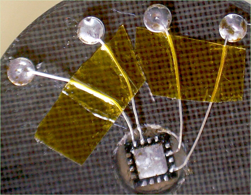
Deadbug
Blank Teflon Composite Pcb, Turret Pins
Neat, functional, minimal, reliable.
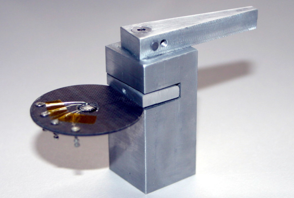
PCB Vice
A small vice to clamp pcbs securely for microscope work is essential. This is my first version and only needs a 3mm ‘bite’ to clamp firmly.
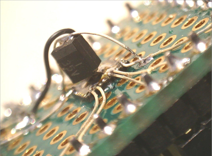
Matrix Board
My first ever STM32F051 32QFN deadbug, difficult and messy, this is the predecessor to the picture above featuring turret pins and shows the evolution of my designs.
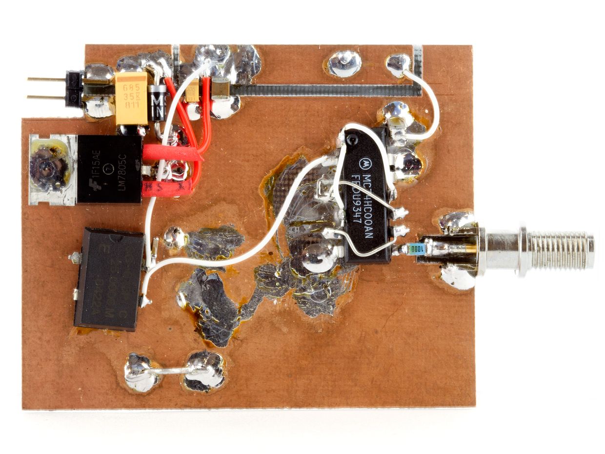
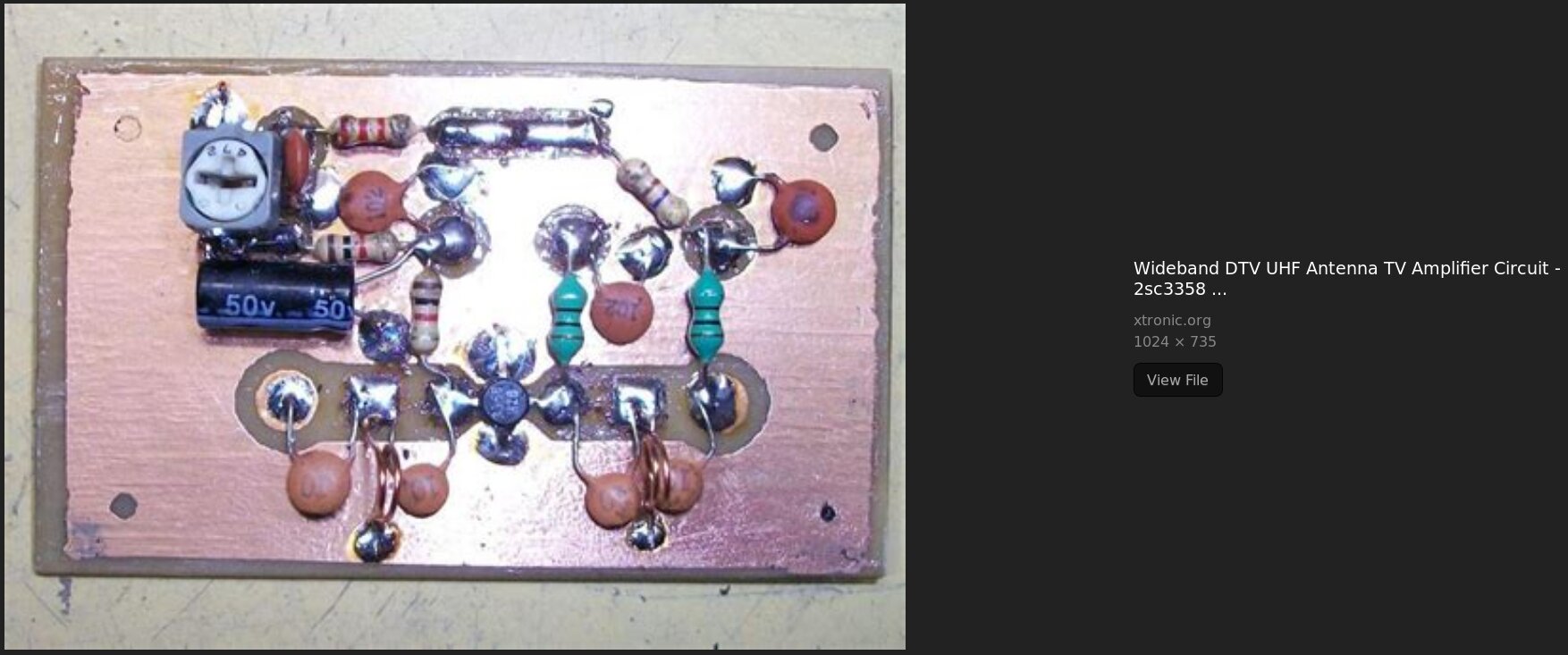
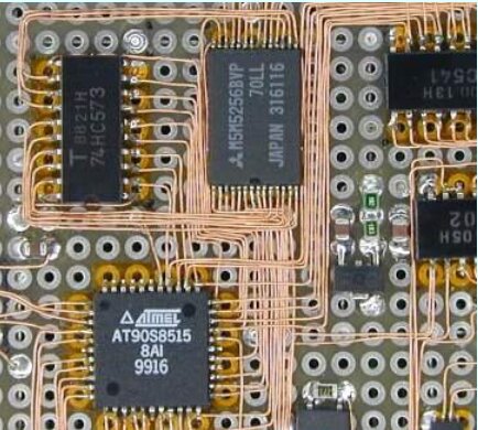
Blank Copper Pcb
Remember, what looks untidy to you, may look perfect to a electron!
The designer used the tried and true method of feeding the longer wires under other wires and chips to keep them tied down. Dots of Superglue can also be used to keep the wires tidy and in place. Etchant or acid to provide electrical isolation (messy, but perhaps the designer wanted to reduce capacitance, but if not, Kapton tape would have looked better imho) also appears to have been smeared on the pcb to remove copper as was a boxcutter knife and ruler straight edge.
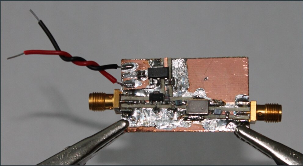
Island Method
Neat RF layouts
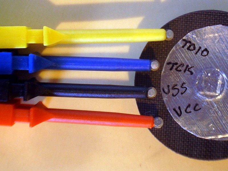
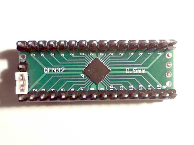
Tp on Headerboard
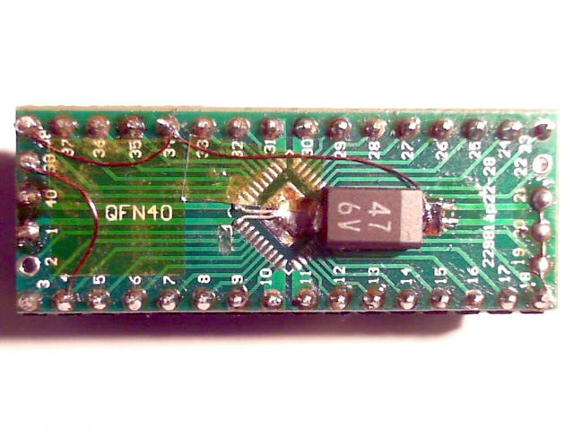
Working prototype built on Cheap Chinese headerboard. This is running Forth on a STM32F051 in 32 pin QFN chip hand soldered with hot air gun. The option jumper is for boot-mode selection for serial flashing.
Top
Bottom
Elmchan. SMT On Matrixboard
Perfection, skill, ZEN
Tp, SMT on Matrixboard
Messy, no fun to make, ugly
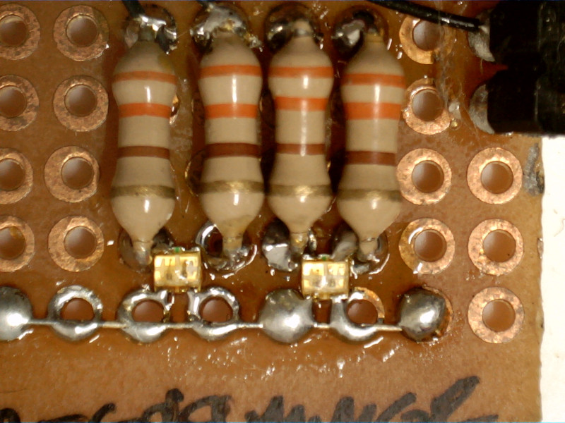
Tp, Dip and SMT on Matrixboard
Horrible … those are dual color SMT LEDs
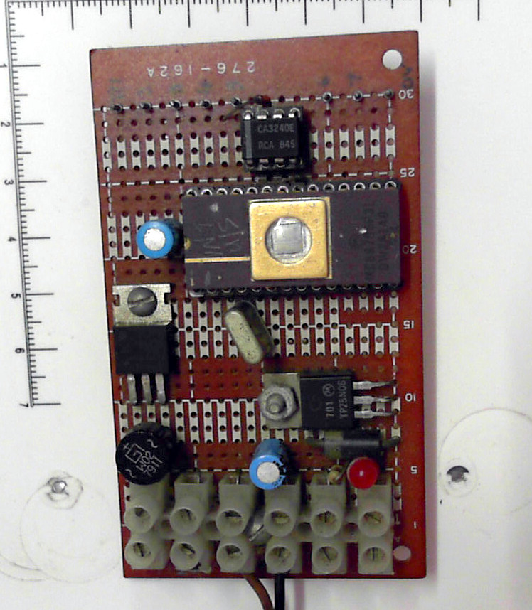
Tp, DIP on Matrixboard
Very old, I made this in 198x, the windowed chip is a Motorola 6805 with on board EPROM.
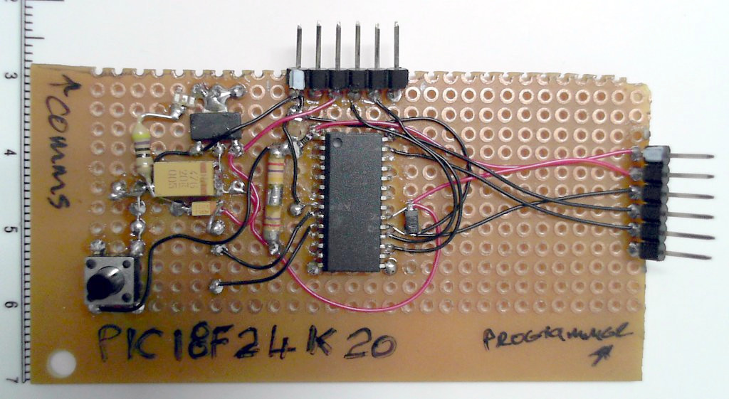
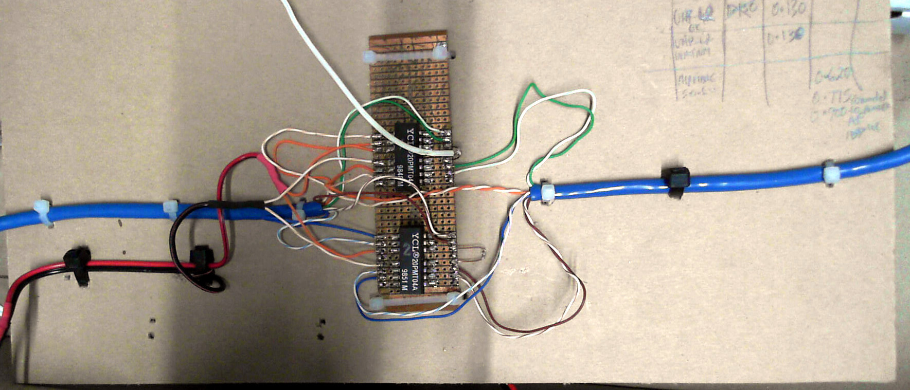
Tp, Dip, Veroboard and Wiring
How to hold everything including wiring in a stable, secure layout that also allows notes, labelling and is easy to move. Cardboard and cable ties, easy to do, long lasting.
This is part of a Gigabit Ethernet POE powermeter design I was prototyping.
BreadBoard
Don’t, just don’t! The design is very temporary, it will work when its made, but tomorrow, next week, next month, when a wire is pulled out, falls out, etc it won’t work.
Breadboard Negatives
A breadboarded device is like a photograph, it only captures the moment you took the picture
They are for DIP IC use only, NO header pins !
Pcb headers jammed into the breadboard makes the contact weak and later IC connections (and gripping) in the same locations become intermittent. - BAD
Connections provide the mounting - BAD
Vibration can cause connections faults - BAD
High capacitance
High inductance
no ground plane, lots of noise and mains hum
Only cheap junk available now. A high quality plug in board with gold plated wipers is very expensive … if you can find one.
Low current capacity
Forget about developing low noise or high speed circuits on one.
Forget about reliability
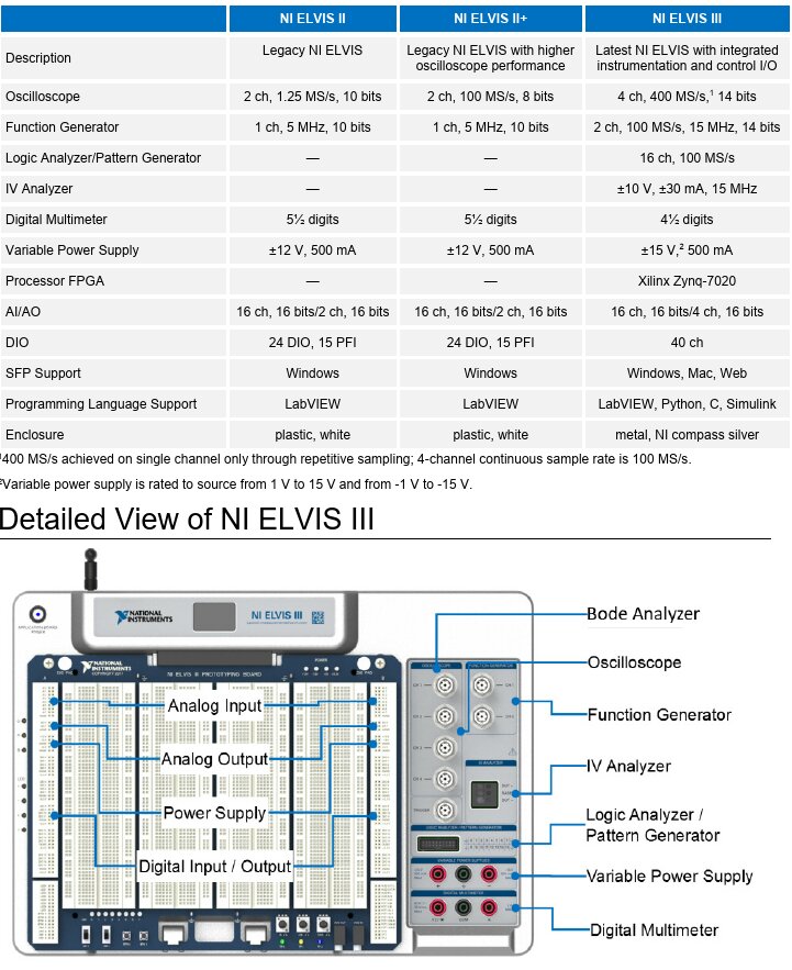
Having said all that, this one by National Instruments is probably well designed, the price is $5500.00 AUD.
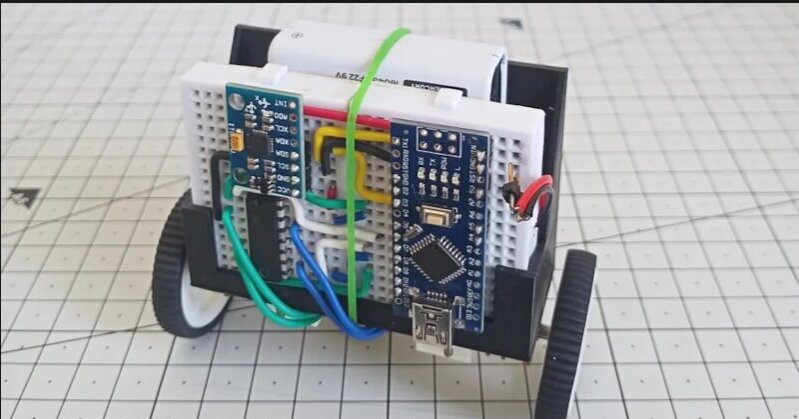
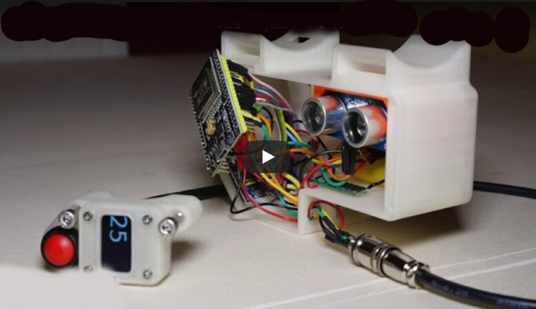
Devboard
Great 3d printed enclosure, I like the design but including an off the shelf devboard is just problematic. The enclosure has to be much bigger to accomodate it compared to a custom board, and all those wires and Dupont jumpers are asking for problems.
Summary
DIP parts are much more expensive and they only provide the illusion of ‘being easy to use’ in breadboards.
SMT parts are cheap and easy to use, with the right tools and equipment, so why not bypass the problems of DIP parts and breadboards, the electrical noise, the intermittent connections and make your prototypes using permanent construction methods ?
