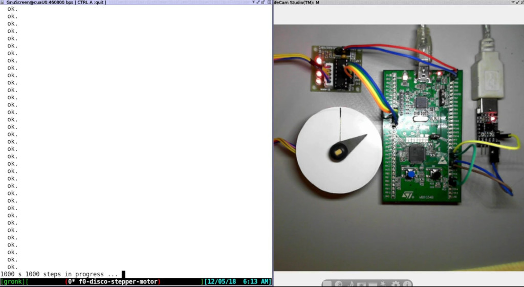
Stepper Motor Demo
A real time Forth Stepper Motor driver demo.
Short Youtube Video
https://www.youtube.com/watch?v=0gGkwmRNnGA
Hearing Impaired
For the Hearing Impaired (or those that can’t understand my mumbling)
Download script.txtfor the video.
Parts Used
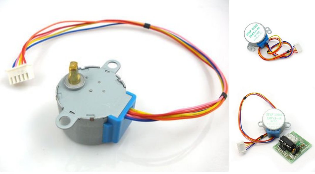
A STM32F0 ‘Discovery Board’
USB/3.3v dongle
Stepper motor and driver board: https://www.instructables.com/id/BYJ48-Stepper-Motor/
Fourth Source Code
\ Program Name: f0-disco-stepper-motor.fs
\ This program may require other support files listed in preload.sh which need to be loaded first
\ Date: Sat 1 Dec 2018 13:18:58 AEDT
\ Copyright 2018 t.porter <terry@tjporter.com.au>, licensed under the GPL
\ For Mecrisp-Stellaris by Matthias Koch.
\ https://sourceforge.net/projects/mecrisp/
\ Chip: STM32F051, Board: STM32F0 Discovery Board
\ Clock: 8 Mhz using the internal STM32F051 RC clock, unless otherwise stated
\ All register names are CMSIS-SVD compliant
\ Note: gpio a,b,c,d,e, and uart1 are enabled by Mecrisp-Stellaris Core.
\
\ This Program : Is a stepper motor controller. Controlled from the terminal "100 steps" result in 100 clockwise steps,
\ "-100 steps" in 100 anticlockwise steps. Program to have a absolute-steps counter
\
\ http://forth.org/library/eforth_SOC/eforth_SOC_source/eForth1/68eforth.zip
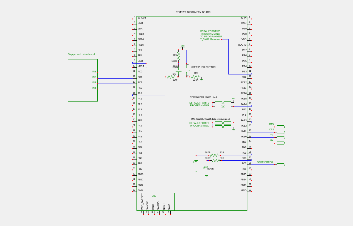
\ Stepper: GPIOC: bits 0 - 3
\
\ 28-BYJ48 Stepper motor.
\
\ Forward Steps
\ STEP PH4 PH3 PH2 PH1
\ 1 OFF OFF OFF ON
\ 2 OFF OFF ON OFF
\ 3 OFF ON OFF OFF
\ 4 ON OFF OFF OFF
\
\ Reverse Steps
\ STEP PH4 PH3 PH2 PH1
\ 1 ON OFF OFF OFF
\ 2 OFF ON OFF OFF
\ 3 OFF OFF ON OFF
\ 4 OFF OFF OFF ON
\
\
\ ---------------------------------------------------------------------------\
1 constant ph1
2 constant ph2
4 constant ph3
8 constant ph4
$F constant phase-mask
0 variable steps
0 variable absolute-steps
0 variable counter
1 variable flag
%0001 variable motor
: init.stepper \ set pins as outputs
OUTPUT 6 lshift $48000800 bis! \ GPIOC_MODER_MODER3
OUTPUT 4 lshift $48000800 bis! \ GPIOC_MODER_MODER2
OUTPUT 2 lshift $48000800 bis! \ GPIOC_MODER_MODER1
OUTPUT 0 lshift $48000800 bis! \ GPIOC_MODER_MODER0
%0001 phase-mask and GPIOC_ODR !
;
: zero ( 0 -- ) 0 absolute-steps ! ." step position counter reset " cr ; \ Zero the absolute-steps counter when the pointer is aligned to the black line on the white dial
: delay 0 do pause loop \ delay to give the stepper coils enough time to reach peak current
;
: motor-driver ( phase pattern -- ) \ sends the stepper phase pattern to GPIOC:0-3 without intefering with other bits
phase-mask and GPIOC_ODR ! \ mask the stepper drive value with the phase-mask then write to GPIOC
1000 delay \ delay by 1000 clock cycles, more or less. It's only arbitary, basically if the delay is too short the stepper won't move.
; \ if it's too long, the stepper will rotate too slowly
: forward-one-step ( -- ) \ motor ONE step forward
motor @ ph4 = if ph1 motor ! \ if motor is at phase 4 already, next step is phase 1
else motor @ shl motor ! \ shift the pattern 1 left
then
motor @ motor-driver \ send the new pattern to the stepper
;
: reverse-one-step ( -- ) \ motor ONE step backward-one-step
motor @ ph1 = if ph4 motor ! \ if motor is at phase 1 already, next step is phase 4
else motor @ shr motor ! \ shift the pattern 1 right
then
motor @ motor-driver \ send the new pattern to the stepper
;
: forward ( steps -- ) \ forward required steps
begin
pause
forward-one-step
1 - dup 0 > while \ one forward step completed, subtract it and test if all steps are done
repeat \ all steps not done, go back to begin
drop \ all steps done, drop the duplicate
;
: reverse ( steps -- ) \ reverse required steps
begin
pause
reverse-one-step
1 - dup 0 > while \ one reverse step completed, subtract it and test if all steps are done
repeat \ all steps not done, go back to begin
drop \ all steps done, drop the duplicate
;
: s ( steps -- ) \ Step controller Word, determines if steps will be forward or reverse
>r r@ . ." steps in progress ... " \ Use the Return Stack as a local variable
r@ 0 > if \ Go UP-MODE
absolute-steps @ r@ + absolute-steps ! \ update absolute step count
r@ forward \ send required steps to direction control
else
r@ 0 < if \ Go DOWN-MODE
absolute-steps @ r@ + absolute-steps ! \ update absolute step count
r@ abs reverse \ convert negative steps to absolute, send to direction control
then then
r> drop \ balance Return Stack
." steps completed, absolute steps: " absolute-steps @ . cr \ print absolute step count
pause
;
: r 2048 * s ; \ Rotate X complete rotations (2048 steps per rotation)
\ ------------------- below here only used with multasking.fs, not needed otherwise -----------------------------\
\ ------ If not using multitasking.fs, delete/comment-out all occurrences of the Word "pause" in this file -------\
: main
pause \ essential Word
;
: init-general \ essential multitasking and initialization Word
f0-disco-48mhz
init.stepper
;
Schematic
Sophisticated Stepper Driver
This much more sophisticated stepper driver example with comprehensive readme and comments by Andrew Palm may be found in the Mecrisp-Stellaris Distribution, STM32F051 directory.
Andrews stepper driver uses a cheap mechanical rotary encoder to control the stepper rotation and vary the brightness of a LED, depending on a push button selectable mode.
As it happens, we both use exactly the same stepper motor and driver board, which being low power is a good choice for USB powered projects.
Readme
---------------------------------------------------------------------------
This folder contains a set of examples using Mecrisp-Stellaris Forth by
Matthias Koch.  They were written for an STM32F051K8T6 on a DIP conversion
PCB and components on a solderless breadboard.  They are listed here in
approximately increasing order of complexity.

These examples were adapted from exercises developed while learning C
programming for MSP430 and STM32F1/F0 chips using two primary sources:

  - "MSP430 State Machine Programming" by Tom Baugh, 2008
  - "Discovering the STM32 Microcontroller" by Geoffery Brown, 1992

Andrew Palm
February 2018

---------------------------------------------------------------------------
example-delay.fs - This is a relatively simple "blinky" example.  However,
it introduces code to set the system clock to 48 MHz using the PLL and
internal 8 MHz RC oscillator.  Blocking delays are used for an approximate
1 Hz blink rate, with the delay count values derived empirically.  Also
introduced is the "init" word, which executes on a chip reset.  The main
program is set up inside this word's definition.  In order to make the
interpreter available after the program is started with a reset, the
bottom of the main loop has the "key? until" construct so that pushing
any key on the serial terminal will halt the loop.  A "reset" command will
restart the program.

---------------------------------------------------------------------------
example-pb-poll.fs - This example is a significant jump up in complexity.
It uses the SysTick counter and interrupt to implement a main loop which
repeats every 1 millisecond.  This provides a time base for program tasks
so that blocking delays are not needed in the main loop.  Also introduced
are "drivers" for a pushbutton and rotary encoder that control two leds.
The tasks which directly control the leds "register" with these drivers
so that the desired control happens.  Why introduce this complication?
The reason is that in more complicated programs the functions of the
pushbutton and rotary encoder can be changed "on the fly" by registering
different "event sinks" or "actions" with them.  This is especially useful
when implementing menus.  (See example-servo.fs below.)

The pushbutton driver allows for two actions, one for a short push and
one for a long (> 1 sec) push.  In this example a short push turns on led2
and a long push turns it off.  It also does software debouncing.  The
encoder driver assumes that its input connections are debounced in
hardware and has cw and ccw actions.  In this example a cw turn of the
encoder increases the flashing led1 duty cycle, and a ccw turn decreases
the duty cycle.

The comment header in the file gives details on the hardware connections.
It also contains comments on making the hardware setup stand-alone.
Because of the "key? until" construct that allows escape from the main
loop, if the terminal is disconnected, the program halts.  To defeat this,
the USART RX connection on PA10 can be held at 3.3 volts by a jumper.

---------------------------------------------------------------------------
example-pb-int.fs - This is identical in hardware to the previous example,
but the pushbutton now uses an external interrupt rather than polling.
This introduces code which sets up an external interrupt and sets its
priority.  This example also sets the priority of the SysTick interrupt.

Note that control of the second led by the pushbutton now runs completely
in the background, as the main loop does not contain a task for it.

---------------------------------------------------------------------------
example-servo.fs - This example adds a third led and a servo motor.  It
shows how to set up a timer to produce a pwm output, in this case to
control the servo motor position.  (The servo motor is very small to avoid
current draw beyond the breadboard power supply.)  The example also shows
the advantage of using the pushbutton and rotary encoder driver
registration, as described above, by having two "control modes."

When the pushbutton is given a long push the control mode is toggled.
In "Mode 0" the encoder increases and decreases the duty cycle of the
flashing led, and the pushbutton toggles the second led on and off with a
short push.  In "Mode 1" the encoder controls the position of the servo
motor, and a short push on the pushbutton centers the servo position.  The
third led serves as a mode indicator, off in Mode 0 and on in Mode 1.
The driver registrations for the two control modes are made using the task
cntl-mode, which is registered with the pushbutton long push.

---------------------------------------------------------------------------
example-stepper.fs - This example is similar to the servo motor example,
except that a 28BYJ-48 5V stepper motor with gear reduction and a ULN2003A
darlington driver board is used instead (see eBay).  Another difference is
when in "Mode 1" the pushbutton simply stops the motor in its current
position rather than returning it to a neutral position.  The incremental
motor steps are done every 5 ms (five main loop ticks), and half-stepping
is used.

---------------------------------------------------------------------------
example-adc.fs - This example uses a third led and a 10 Kohm potentiometer
in the hardware.  The wiper of the pot is input to the ADC, which does a
conversion every 10 ms, triggered by a timer.  The third led is turned on
when the pot wiper voltage is above one half the supply voltage.

The control of the third led using the adc, like the pushbutton control of
the second led, is completely in the background.

---------------------------------------------------------------------------
example-ultrasonic.fs - This example uses two timers to trigger and
measure the returned echo pulse from an ultrasonic distance sensor.  The
timer setup code is more complicated than in the previous example, esp.
since the time processing the returned echo pulse must use two capture
and compare channesl to measure the pulse width.  Although the sensor is
triggered every 100 ms, the calculation and distance display task is run
every 200 ms in the main loop to keep the terminal output reasonable.
One could change the trigger period and do the calculation and display in
the background.

---------------------------------------------------------------------------
example-nunchuk-i2c.fs - This example uses I2C to communicate with a Wii
nunchuk, which contains two pushbuttons, a joystick, and an accelerometer.
The raw data from the nunchuk are read over I2C and then converted to
values for display on the serial terminal.  The I2C drivers can be
configured for 100 kHz or 400 kHz communication and can send or receive
up to 255 bytes with one call.  Error messages can be uncommented to help
debug problems.

Another feature introduced with this example is the use of state machines
to break up tasks into smaller parts.  The reason for this is that a task
called from the main loop may take so long to execute that it could not be
completed within the time allowed for a single loop, esp. when other tasks
must also be completed in the loop time (in this case 1 ms).  This simple
version of a state machine uses the forth "case" structure.  On each call
of the task, one of the "of ... endof" pieces is executed.  A "state
variable" value controls which piece is executed.  State machines are used
for the tasks nchk-read and nchk-display.

---------------------------------------------------------------------------
example-ssd1306.fs - Here we use I2C to write to a small 32x128 OLED
display which is used as a 4 row by 21 column character display.  The
drivers write text strings to the display in either non-scrolling or
scrolling mode.  This example displays messages in scrolling mode when the
leds are changed by the pushbutton or rotary encoder.  The task which
draws the characters on the display is called in the main loop and uses a
state machine which loops through the 84 character positions, drawing one
character per loop.  With loop initialization, the display is updated
completely every 85 ms.

** Note: This example uses a second file named glcdfont.fs.  There is an
         #include directive in the main file to pull the glcdfont.fs code
         into the main file when it is downloaded via the serial terminal.
         This directive is for the e4thcom program.  If you do not use this
         particular terminal program, you can cut and paste glcdfont.fs
         into example-ssd1306.fs at the place where the directive is, or
         modify the include directive for your setup.

---------------------------------------------------------------------------
example-st7735.fs - This is very similar to example-ssd1306.fs in
operation, but it uses an Adafruit 160x128 TFT display module connected
by SPI instead of I2C.  The display is color and graphical, but it is used
as a monochrome character display with 12 rows and 26 columns with a blue
background and yellow characters.  (The font and background colors are
easy to change.)  The SPI1 drivers in this example can be used for other
devices, such as sensors.

---------------------------------------------------------------------------
Makefile - This is a script for the program make, which is usually used to
organize the compiling and linking of programs.  Here it is a convenient
way to invoke terminal commands to flash or bootload the forth kernel to
the chip and to connect a serial terminal emulator program to the chip once
forth is running.

---------------------------------------------------------------------------
Final comments.  You can create your own examples by mix-and-matching
parts of these examples.  For example, the servo motor example could be
modified to include the ssd1306 display.  The display could show which
control mode has been selected and show messages when a particular control
action is made.

Due to the designed-in upward compatibility of STM32 mcu's, these examples
should be easily adapted for larger chips in the STM32F0 family, and for
the smaller STM32F030K6T6, which has an identical pinout to the K8T6.  Do
note, however, that interrupt names should be checked for the forth kernel
you are using.

If you use an external 8 MHz crystal instead of the internal oscillator,
the 48MHz code must be changed.  Modifications would also be necessary for
a Nucleo board whose clock is driven by an external source.
Example-stepper.fs
\ =========================================================================
\  Program Name: example-stepper.fs for Mecrisp-Stellaris by Matthias Koch
\
\  This program is a template for larger projects, as it includes a main
\  loop controlled by the SysTick timer.  There are these tasks:
\
\     - A flashing yellow led with variable duty cycle controlled by a
\       rotary encoder.
\     - A green led that is toggled by a short push on a pushbutton
\     - A red led that indicates the control mode (see below)
\     - A pushbutton driver (interrupt version)
\     - A driver for a rotary encoder with alternate detents
\     - A small stepper motor which is also controlled by the pushbutton
\       and rotary encoder
\     - When a long (> 1 sec) push is made on the pushbutton, the control
\       toggles between two modes:
\         Mode 0: Red led off
\                 The pushbutton toggles the green led on and off
\                 The rotary encoder controls the duty cycle of the yellow
\                 led
\         Mode 1: Red led on
\                 The pushbutton immediately stops the motor
\                 The rotary encoder controls the stepper motor
\
\  Hardware:
\     - STM32F051K8T6 on DIP conversion board
\     - Two leds, yellow on PF0, green on PF1 (330 ohm dropping resistors)
\     - A red led on PA6 (330 ohm dropping resistor)
\     - Pushbutton with internal pullup and software debounce on PA4
\     - Rotary encoder with 30 alternate detents on PA0 and PA1 with
\       internal pullups and hardware debounce.
\     - Small 28BYJ-48 5V stepper motor driven by ULN2003A darlington
\       driver (from eBay) with these connections:
\
\       Driver board      STM32
\           Ch1            PA8
\           Ch2            PA12
\           Ch3            PA11
\           Ch4            PA15
\            V-            Grnd
\            V+            5V from USB-to-serial board
\
\       Note:  These connections are so that the direction of rotation
\              facing the motor is the same direction as the rotary
\              encoder direction.  To reverse this, reverse the order of
\              the channel connections above.
\
\ -------------------------------------------------------------------------
\  To run stand-alone:
\     - This example uses the "init" word so that the main program will
\       run on a reset by the reset button or a terminal command.
\     - The main loop uses "key? until" so that when running with a
\       terminal connected (PA9 TX and PA10 RX) a key press can break
\       execution.
\     - However, if the terminal RX connection on PA10 is removed, the
\       program hangs due to the use of key? in the main loop.
\     - To allow the program to run without the terminal but retain the
\       use of key? for possible later updating or debugging, connect PA10
\       to 3.3V (VDD) when not using the terminal (or just using TX on PA9).
\
\ -------------------------------------------------------------------------
\  Style:
\     - All words are in lower case with parts separted by hyphens.
\     - Constants are in upper case, with parts separated by
\       underscores.
\     - Variables and words associated with a task are prefixed by the
\       task name (which is in lower case) with subsequent parts of
\       variable names having the initial letter in upper case and
\       separated by hyphens.
\     - Variables acting as function pointers (containing the address
\       of a word) have a tick prefix.
\ -------------------------------------------------------------------------
\  Andrew Palm
\  2018.02.08
\ =========================================================================

compiletoflash
\ -------------------------------------------------------------------------
\  Core and peripheral registers
\ -------------------------------------------------------------------------
$E000E010 constant SysTick
  SysTick $00 + constant SysTick_CTRL
  SysTick $04 + constant SysTick_LOAD
  SysTick $08 + constant SysTick_VAL
  SysTick $0C + constant SysTick_CALIB

$E000E100 constant NVIC
  NVIC $000 + constant NVIC_ISER
  NVIC $180 + constant NVIC_ICPR
  NVIC $300 + constant NVIC_IPR0

$E000ED00 constant SCB
  SCB $01C + constant SCB_SHPR2

$40021000 constant RCC
  RCC $00 + constant RCC_CR
  RCC $04 + constant RCC_CFGR
  RCC $14 + constant RCC_AHBENR
  RCC $18 + constant RCC_APB2ENR
  RCC $1C + constant RCC_APB1ENR

$40022000 constant FLASH
  FLASH $0 + constant FLASH_ACR

$40010000 constant SYSCFG
  SYSCFG $0C + constant SYSCFG_EXTICR2

$40010400 constant EXTI
  EXTI $00 + constant EXTI_IMR
  EXTI $04 + constant EXTI_EMR
  EXTI $0C + constant EXTI_FTSR
  EXTI $14 + constant EXTI_PR

$48000000 constant GPIOA
  GPIOA $00 + constant GPIOA_MODER
  GPIOA $04 + constant GPIOA_OTYPER
  GPIOA $08 + constant GPIOA_OSPEEDR
  GPIOA $0C + constant GPIOA_PUPDR
  GPIOA $10 + constant GPIOA_IDR
  GPIOA $18 + constant GPIOA_BSRR
  GPIOA $20 + constant GPIOA_AFRL
  GPIOA $28 + constant GPIOA_BRR

$48001400 constant GPIOF
  GPIOF $00 + constant GPIOF_MODER
  GPIOF $14 + constant GPIOF_ODR
  GPIOF $18 + constant GPIOF_BSRR
  GPIOF $28 + constant GPIOF_BRR

$40013800 constant USART1
  USART1 $C + constant USART1_BRR

$40002000 constant TIM14
  TIM14 $00 + constant TIM14_CR1
  TIM14 $14 + constant TIM14_EGR
  TIM14 $18 + constant TIM14_CCMR1
  TIM14 $20 + constant TIM14_CCER
  TIM14 $28 + constant TIM14_PSC
  TIM14 $2C + constant TIM14_ARR
  TIM14 $34 + constant TIM14_CCR1

\ -------------------------------------------------------------------------
\  Misc. helper words, constants, and variables
\ -------------------------------------------------------------------------
\  Null (event sink) action used by pushbutton and rotary encoder tasks.
: null-act ( -- )  nop ;


\ Wait while the word test with address 'test results in a true, or until
\ timeout ends.  Returns status = 0 if exits before timeout, returns
\ status = 1 if timeout occurs.
\ : timed ( 'test -- status )
    \ $FFFF                             \ Timeout value
    \ begin swap dup execute while
      \ swap 1- dup 0= if
        \ 2drop 1 exit                  \ Timed out
      \ then
    \ repeat
    \ 2drop 0                           \ 'test became false before timeout
\ ;

\ Blocking delays (approximate) for 48 MHz system clock
\ 52000 constant LOOPS/MS
\ : ms-delay ( n -- )   LOOPS/MS * 4 rshift 0 DO nop LOOP ;

52 constant LOOPS/US
: us-delay ( n -- )   LOOPS/US * 4 rshift 0 DO nop LOOP ;

\ Aids to simple printing
\ : hex.dec ( n|u -- )  hex . decimal ;
\ : tab ( -- )  9 emit ;

: h><, ( hx -- )
  dup $00FF and 8 lshift
  swap $FF00 and 8 rshift
  or h,
;
\ -------------------------------------------------------------------------
\  Clock setup and timing plus USART1 baud set to 115200 for cortex-m0.
\  Uses 8 MHz internal oscillator divided by 2 and x12 PLL multiplier.
\
\  Clock initialization code is modified from usb-f1.txt by Jean-Claude
\  Wippler.
\  Adjusted for STM32F051 @ 48 MHz (original STM32F100 by Igor de om1zz).
\ -------------------------------------------------------------------------
: 48MHz ( -- )
\ Set the main clock to 48 MHz, keep baud rate at 115200

  %1 RCC_CR bis!                        \ set HSION
  begin %1 1 lshift RCC_CR bit@ until  \ wait for HSIRDY

  %10001 FLASH_ACR !    \ One flash wait state, enable prefetch buffer

  \ HSI clock /2 = 4 MHz source for PLL
  %1111 18 lshift RCC_CFGR bic!
  %1010 18 lshift RCC_CFGR bis!   \ PLL factor: 4 MHz * 12 = 48 MHz

  %1111 4 lshift RCC_CFGR bic!    \ HPRE DIV 1, HCLK = SYSCLK
  %111  8 lshift RCC_CFGR bic!    \ PPRE DIV 1, PCLK = HCLK

  %1 24 lshift RCC_CR bis!                \ set PLLON
  begin %1 25 lshift RCC_CR bit@ until    \ wait for PLLRDY

  %11 RCC_CFGR bic!
  %10 RCC_CFGR bis!               \ PLL is system clock

  $1A1 USART1_BRR !               \ Set console baud rate to 115200
;

\ -------------------------------------------------------------------------
\  Set up SysTick for main loop 1 ms tick
\ -------------------------------------------------------------------------
1 constant MAIN_TICKS  \ Number of systicks for main loop repeat
MAIN_TICKS variable main-Tick-Cnt

1 constant SysTick_PRIORITY
-1 constant SysTick_IRQn

: systick-handler ( -- )
  main-Tick-Cnt @ if
    -1 main-Tick-Cnt +!
  then
;

: wait-for-tick ( -- )
  begin main-Tick-Cnt @ 0= until
  MAIN_TICKS main-Tick-Cnt !
;

: systick-init ( -- )
  %011 SysTick_CTRL bic!    \ Disable timer and interrupt
  48000 1 - SysTick_LOAD !  \ (SystemCoreClock/1000)-1 for 1 ms tick
  0 SysTick_VAL !
  %101 SysTick_CTRL bis!    \ Set CLKSOURCE, ENABLE bits

  \ Set SysTick interrupt priority
  SysTick_PRIORITY 6 lshift $FF and  \ Priority byte
  SysTick_IRQn %11 and 3 lshift      \ Bit shift
  lshift
  SysTick_IRQn %1111 and 8 - 2 rshift 2 lshift  \ Byte offset from SCB_SHPR2
  SCB_SHPR2 + bis!                    \ Write priority bits

  ['] systick-handler irq-systick !   \ Register systick-handler
  %010 SysTick_CTRL bis!    \ Enable system tick interrupt (bit TICKINT)
;

\ -------------------------------------------------------------------------
\  Initialize gpio peripheral clocks and pins
\ -------------------------------------------------------------------------
7 constant EXTI4_15_IRQn
2 constant EXTI4_15_PRIORITY

: gpio-init ( -- )
  \ Enable GPIOF peripheral clock and set pins PF0 and PF1 as output
  \ (push-pull, low speed) for leds
  %1 22 lshift RCC_AHBENR bis!
  %0101 GPIOF_MODER !

  \ Enable GPIOA peripheral clock and set pins PA0, PA1, and PA4 to
  \ input with internal pullups
  %1 17 lshift RCC_AHBENR bis!
  %01 8 lshift %01 2 lshift or %01 or GPIOA_PUPDR bis!

  \ Set up external interrupt on PA4
  %111 SYSCFG_EXTICR2 bic!    \ Assign PA4 to EXTI line 4(reset value)
  %1 4 lshift EXTI_IMR bis!   \ Enable interrupt, line 4
  %1 4 lshift EXTI_FTSR bis!  \ Falling edge trigger enabled, line 4
  %1 4 lshift EXTI_EMR bis!   \ Enable event, line 4
  \ Set interrupt priority
  EXTI4_15_PRIORITY 6 lshift $FF and  \ Priority byte
  EXTI4_15_IRQn %11 and 3 lshift      \ Bit shift
  lshift
  EXTI4_15_IRQn 2 rshift 2 lshift     \ Byte offset from NVIC_IPR0
  NVIC_IPR0 + bis!                    \ Write priority bits
  \ Enable interrupt
  %1 EXTI4_15_IRQn lshift NVIC_ISER bis!

  \ Set pin PA6 as output for led (push-pull, low speed)
  %01 12 lshift GPIOA_MODER bis!

  \ Set pins PA8, PA11, PA12, and PA15 as output to stepper motor
  \ (push-pull, low speed)
  %01 16 lshift %01 22 lshift or %01 24 lshift or %01 30 lshift or
  GPIOA_MODER bis!

;

\ -------------------------------------------------------------------------
\  Pushbutton driver for pushbutton pb0 on pin PA4 with software debounce.
\  This is an interrupt version that assumes that pb1-task is called in the
\  main loop.  The interrupt is used to start a timer on a falling edge.
\  Input pin value is assumed low on push, high (pulled up) on release.
\  Pushbutton action occurs when button is released.
\  There are two types of pushes, short (<= 1 sec) and long (> 1 sec).
\  A client task registers short and long push actions (event sinks)
\  by loading the associated word addresses into the pointer variables
\  'pb1-Short-Act and 'pb1-Long-Act, resp.
\ -------------------------------------------------------------------------
%1 4 lshift constant PB1_MSK

PB1_MSK variable pb1-Val
0 variable pb1-Timer-Cnt
0 variable pb1-Timer-On?

' null-act variable 'pb1-Short-Act
' null-act variable 'pb1-Long-Act

: pb1-get ( -- )  GPIOA_IDR @ PB1_MSK and pb1-Val ! ;

: pb1-handler
  \ If falling edge detected on PA4, start pushbutton timer
  EXTI_PR @ PB1_MSK and if    \ Interrupt for EXTI line 4 asserted?
    1 pb1-Timer-On? !         \ Turn timer on
    PB1_MSK EXTI_PR bis!      \ Reset the interrupt flag
  then
;
: pb1-init ( -- )
  pb1-get
  ['] null-act 'pb1-Short-Act !
  ['] null-act 'pb1-Long-Act !
  ['] pb1-handler irq-exti4_15 !    \ Register systick-handler
;

: pb1-task
  pb1-Timer-On? if
    1 pb1-Timer-Cnt +!    \ Increment timer
    pb1-get
    pb1-Val @ PB1_MSK = if    \ Button released?
      pb1-Timer-Cnt @ 1000 > if   \ Long push if more than 1000 main ticks
        'pb1-Long-Act @ execute
      else
        pb1-Timer-Cnt @ 20 > if   \ Debounce delay 20 main loop ticks
          'pb1-Short-Act @ execute
        then
      then
      0 pb1-Timer-Cnt !   \ Reset timer count
      0 pb1-Timer-On? !   \ Turn timer off
    then
  then
;

\ -------------------------------------------------------------------------
\  Rotary encoder driver (alternating detent type) on PA0 and PA1.
\  (If encoder does not have alternating detents, see comment below.)
\  If the encoder is mechanical, it is assumed that the channels are
\  debounced in hardware.
\  This is a polling version that assumes that pb1-task is called in the
\  main loop.  Input pins are pulled up.
\  A client task registers clockwise and counter-clockwise actions (event
\  sinks) by loading the associated word addresses into the pointer
\  variables 'enc1-CW-Act and 'enc1-CCW-Act, resp.
\ -------------------------------------------------------------------------
' null-act variable 'enc1-CW-Act
' null-act variable 'enc1-CCW-Act

%01 constant CH_A_MSK
%10 constant CH_B_MSK

CH_A_MSK variable enc1-ChA-Val
CH_A_MSK variable enc1-ChA-Last-Val
CH_B_MSK variable enc1-ChB-Val

: enc1-cha-get ( -- )  GPIOA_IDR @ CH_A_MSK and enc1-ChA-Val ! ;

: enc1-chb-get ( -- )  GPIOA_IDR @ CH_B_MSK and enc1-ChB-Val ! ;

: enc1-init ( -- )
  enc1-cha-get
  enc1-chb-get
  enc1-ChA-Val @ enc1-ChA-Last-Val !
;

: enc1-task ( -- )
  enc1-cha-get
  enc1-chb-get

  enc1-ChA-Val @ 0= enc1-ChA-Last-Val @ 0<> and if
    enc1-ChB-Val @ 0<> if
      'enc1-CW-Act @ execute
    else
      'enc1-CCW-Act @ execute
    then
  then

  \ If rotary encoder does not have alternating detents, comment out
  \ the if-then below
  enc1-ChA-Val @ 0<> enc1-ChA-Last-Val @ 0= and if
    enc1-ChB-Val @ 0<> if
      'enc1-CCW-Act @ execute
    else
      'enc1-CW-Act @ execute
    then
  then

  enc1-ChA-Val @ enc1-ChA-Last-Val !
;

\ -------------------------------------------------------------------------
\  Stepper motor tasks
\ -------------------------------------------------------------------------
' null-act variable 'stpr-Incr

\ Half-step bit pattern bytes for stepper motor.  Patterns are stored in
\ lower nybble of each byte, A channel in bit 0, A-bar in bit 1, B in bit
\ 2, B-bar in bit 3.
\ High and low bytes of halfwords are switched for storage by
\ custom word h<>, so array indices act as if they were for a byte array
\ when accessing it with c@ word.
create A-A/-B-B/
  $0901 h><, $0504 h><, $0602 h><, $0A08 h><,

0 variable stpr-Indx      \ Current bit pattern index

$9900 constant STPR_MSK   \ Bit mask for stepper motor control pins

: stpr-wrt (  -- )
  \ Write current bit pattern to port control pins
  A-A/-B-B/ stpr-Indx @ + c@     \ Get current bit pattern
  $0000                          \ Initialize port pin mask
  over %0001 and 8 lshift or    \ Channel A bit to PA8
  over %0010 and 10 lshift or   \ Channel A-bar bit to PA11
  over %0100 and 10 lshift or   \ Channel B bit to PA12
  over %1000 and 12 lshift or   \ Channel B-bar bit to PA15
  dup not STPR_MSK and GPIOA_BRR bis!   \ Reset zero bits
  GPIOA_BSRR bis! drop                  \ Set one bits
;

: stpr-cw-incr ( -- )
  \ Move stepper motor one incremental step clockwise
  stpr-Indx @ 1 + 8 mod stpr-Indx !
  stpr-wrt
;

: stpr-ccw-incr ( -- )
  \ Move stepper motor one incremental step counter-clockwise
  stpr-Indx @ 1 - dup 0< if
    7 stpr-Indx ! drop
  else
    stpr-Indx !
  then
  stpr-wrt
;

\ The number of main loop ticks for one (arbitrary) unit of rotation
\ corresponding to one encoder detent is 1035.  One of these units is
\ approximately 18 degrees.  There are 1035/5 = 207 incremental motor steps
\ per one of these units.  These values were chosen for a particular motor
\ with high gear reduction and need to be changed for other motors.
1035 constant STPR_TKS/UNIT
5 constant STPR_TKS/STEP

0 variable stpr-Cnt

\ Stop motor in current position (pushbutton client)
: stpr-stop ( -- )
  0 stpr-Cnt !
;

: stpr-task ( -- )
  \ If stpr-Cnt > 0, move motor every STRR_TKS/STEP ticks
  \ in direction determined by function pointer 'stpr-Incr
  stpr-Cnt @ 0 > if
    -1 stpr-Cnt +!
    stpr-Cnt @ STPR_TKS/STEP mod 0= if
      'stpr-Incr @ execute
    then
  then
;

: stpr-cw-step ( -- )
  \ Move motor one step clockwise (client of rotary encoder)
  ['] stpr-ccw-incr 'stpr-Incr @ = if
    ['] stpr-cw-incr 'stpr-Incr !       \ Change direction
    STPR_TKS/UNIT stpr-Cnt !            \ and reset tick count
  else
    STPR_TKS/UNIT stpr-Cnt +!   \ Same directon, incr tick count
  then
;

: stpr-ccw-step ( -- )
  \ Move motor one step counter-clockwise (client of rotary encoder)
  ['] stpr-cw-incr 'stpr-Incr @ = if
    ['] stpr-ccw-incr 'stpr-Incr !       \ Change direction
    STPR_TKS/UNIT stpr-Cnt !             \ and reset tick count
  else
    STPR_TKS/UNIT stpr-Cnt +!   \ Same direction, incr tick count
  then
;

: stpr-init ( -- )
  ['] stpr-cw-incr 'stpr-Incr !
  0 stpr-Cnt !
  0 stpr-Indx !
  stpr-wrt
;

\ -------------------------------------------------------------------------
\  Yellow led task (client of rotary encoder task)
\  Assumes that led is on if output pin is high.
\ -------------------------------------------------------------------------
%1 constant LED1_MSK

500 constant LED1_DFLT_TKS
1000 constant LED1_MAX_TKS
50 constant LED1_MIN_TKS
50 constant LED1_DEL_TKS

LED1_DFLT_TKS variable led1-On-Cnt
LED1_DFLT_TKS variable led1-Off-Cnt
LED1_DFLT_TKS variable led1-Cnt

: led1-dc+ ( -- )
  \ Increase led duty cycle
  led1-On-Cnt @ LED1_DEL_TKS + dup dup LED1_MAX_TKS < if
    led1-On-Cnt !
    LED1_MAX_TKS swap - led1-Off-Cnt !
  else
    drop drop
  then
;

: led1-dc- ( -- )
  \ Decrease led duty cycle
  led1-On-Cnt @ LED1_DEL_TKS - dup dup LED1_MIN_TKS >= if
    led1-On-Cnt !
    LED1_MAX_TKS swap - led1-Off-Cnt !
  else
    drop drop
  then
;

: led1-init ( -- )
  LED1_DFLT_TKS led1-On-Cnt !
  LED1_DFLT_TKS led1-Off-Cnt !
  LED1_DFLT_TKS led1-Cnt !
;

: led1-task ( -- )
  -1 led1-Cnt +!
  led1-Cnt @ 0= if
    GPIOF_ODR @ LED1_MSK and dup if   \ Is led on?
      GPIOF_BRR bis!                  \ Turn led off
      led1-Off-Cnt @ led1-Cnt !       \ Load off tick count
    else
      drop LED1_MSK GPIOF_BSRR bis!   \ Turn led on
      led1-On-Cnt @ led1-Cnt !        \ Load on tick count
    then
  then
;

\ -------------------------------------------------------------------------
\  Green led task (client of pushbutton task)
\  Assumes that led is on if output pin is high.
\ -------------------------------------------------------------------------
%10 constant LED2_MSK

: led2-off ( -- )  LED2_MSK GPIOF_BRR bis! ;

: led2-on ( -- )  LED2_MSK GPIOF_BSRR bis! ;

: led2-tggl ( -- ) LED2_MSK GPIOF_ODR xor! ;

: led2-init ( -- )
  led2-off
;

\ -------------------------------------------------------------------------
\  Red led task (client of control task)
\  Assumes that led is on if output pin is high.
\ -------------------------------------------------------------------------
%1 6 lshift constant LED3_MSK

: led3-off ( -- )  LED3_MSK GPIOA_BRR bis! ;

: led3-on ( -- )  LED3_MSK GPIOA_BSRR bis! ;

\ -------------------------------------------------------------------------
\  Control task
\  Task toggles the control mode when there is a long push on the
\  pushbutton.
\ -------------------------------------------------------------------------
1 variable cntl-Next-Mode  \ Control mode state variable

: cntl-mode-0 ( -- )
  led3-off
  ['] led1-dc+ 'enc1-CW-Act !
  ['] led1-dc- 'enc1-CCW-Act !
  ['] led2-tggl 'pb1-Short-Act !
;

: cntl-mode-1 ( -- )
  led3-on
  ['] stpr-cw-step 'enc1-CW-Act !
  ['] stpr-ccw-step 'enc1-CCW-Act !
  ['] stpr-stop 'pb1-Short-Act !
;

: cntl-mode ( -- )
  \ Set function pointers for new mode, set next mode value
  cntl-Next-Mode @ case
    0 of
      cntl-mode-0
      1 cntl-Next-Mode !
    endof
    1 of
      cntl-mode-1
      0 cntl-Next-Mode !
    endof
  endcase
;

: cntl-init ( -- )
  \ Register with pushbutton long push
  ['] cntl-mode 'pb1-Long-Act !
  \ Initialize in mode 0
  cntl-mode-0
  1 cntl-Next-Mode !
;

\ -------------------------------------------------------------------------
\  Main program that starts on reset
\ -------------------------------------------------------------------------
: init ( -- )

  \ ---------------- Initialization ---------------------------------------
  \ Hardware
  dint          \ Global interrupt disable
  48MHz         \ Set system clock to 48 MHz
  systick-init  \ Set system tick for 1 ms
  gpio-init     \ Initialize port pins and pin interrupts
  eint          \ Global interrupt enable

  \ Tasks
  pb1-init
  enc1-init
  cntl-init
  stpr-init
  led1-init
  led2-init

  \ ---------------- Main loop --------------------------------------------
  begin wait-for-tick
    pb1-task
    enc1-task
    led1-task
    stpr-task
  key? until            \ Escape from main loop on key press
;
\ -------------------------------------------------------------------------
compiletoram
