Serial Terminal: Hardware Flow Control
This is now working, see my RTS patch on how to implement RTS Handshaking on a F0 Disco.
RTS/CTS flow control explained
RTS means “Request To Send”. When this pin stays asserted (positive voltage) at the receiver it means: keep sending data to me.
If RTS is negated (voltage goes negative) it negates “Request To Send” which means: request not to send to me (stop sending).
When the receiver is ready for more input, it asserts RTS requesting the other side to resume sending.
For computers and terminals (both DTE type equipment) the RTS pin sends the flow control signal to the CTS pin (Clear To Send) on the other end of the cable. That is, the RTS pin on one end of the cable is connected to the CTS pin at the other end.
Mecrisp-Stellaris Hardware used
STM32F0 Discovery (Disco) Board
USB/3.3v Serial hardware Option 1
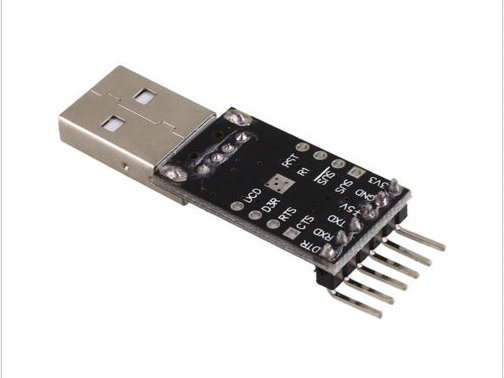
Unix friendly CP2102 chipset dongle, with Rx, Tx, nRTS,nCTS and other control signals, including +5 and +3.3 volts available on pins or holes for pins or wires to be soldered. Usually under $2 on eBay, and the most useful model in my opinion
USB/3.3v Serial hardware Option 2
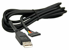
$25 FTDI usb serial cable with RX, TX, GND, 5V DC supply and nCTS and nRTS signals on a 6 pin connector. FT232RQ chip is used. USB Vendor ID (VID): 0403h, USB Product UD (PID): 6001h . Note TX and RX have a internal 270R resistor.
signal |
color |
disco board (AF1) |
|---|---|---|
+5v |
Red |
+5v |
Ground |
Black |
GND |
TX |
Orange (output) |
PA-10 (RX) |
RX |
Yellow (input) |
PA-9 (TX) |
nCTS |
Brown (input) |
PA-12 (RTS) |
nRTS |
Green (output) |
PA-11 (CTS) |
USB/3.3v Serial hardware Option 3
$1 cheap Unix friendly PL2303 chipset usn 3.3v serial dongle (usb3.3v-dongle), but only has TX,RX,0V,+3.3 amd +5V pin.
Note
nCTS and nRTS wires can be soldered onto the PL2303 28 pin SSOP28 chip used in the dongle. These are very fine pitch and it isn’t easy without the right equipment. Theyre also fiddly and fragile so its better to but the Option 1 units above.
PL2303 28 pin SSOP28 Package Pinouts
signal |
pl2303 pin |
|---|---|
nDTR |
2 |
nDSR |
9 |
nDCD |
10 |
nCTS |
11 |
nRTS |
3 |
First Things First, test your serial terminal
The first thing to do is test your serial terminal in loopback, with and without hardware handshaking to make sure it works.
OS: FreeBSD 10.1
Cable: FTDI usb serial cable (option 1 above).
Terminal Program: Picocom
Second, do a Loopback test, with no flow control
Connect the TX and RX wires together and see if the terminal echoes keys typed, if it does then it’s working. If not, possible causes are:- 1) You don’t have permissions to talk to your serial port 2) The wrong serial device is being specified
picocom -b 115200 /dev/cuaU1 –imap lfcrlf,crcrlf –omap delbs,crlf
Third, Loopback with hardware flow control
When /CTS (brown wire) is connected to 0v (LOW), characters typed should be echoed. When /CTS is HIGH the characters should not be echoed.
/RTS (green wire) isn’t used for this test
picocom -b 115200 /dev/cuaU1 --imap lfcrlf,crcrlf --omap delbs,crlf --flow h
Handshaking Timing figure
STM32F0 discovery board mods for hardware flow control
Uses USART1
nCTS: Clear To Send blocks the data transmission at the end of the current transfer when high
nRTS: Request to send indicates that the USART is ready to receive data (when low).
STM32F0 Pin |
Flow control Function |
ALT Configuration |
|---|---|---|
PA12 |
USART1_RTS |
AF1 - 0001 |
PA11 |
USART1_CTS |
AF1 - 0001 |
PA9 |
USART1_TX |
AF1 - 0001 |
PA10 |
USART1_RX |
AF1 - 0001 |
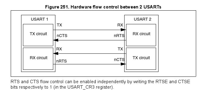
RTS and CTS flow control
can be enabled independently by writing the RTSE and CTSE bits respectively to 1 (in the USART_CR3 register).
STM32F0 RTS flow control
If the RTS flow control is enabled (RTSE=1), then nRTS is asserted (tied low) as long as the USART receiver is ready to receive a new data. When the receive register is full, nRTS is deasserted, indicating that the transmission is expected to stop at the end of the current frame. Figure 252 shows an example of communication with RTS flow control enabled.
CTS
Signal |
I/O |
Description |
|---|---|---|
CTS |
IN |
Clear to send. Indicates whether the UART can start transmitting data when flow control is enabled. |
State |
– Asserted: Data transmission can start. – Negated: Data transmission cannot start. |
|
Timing |
– Assertion When transmitting device’s RTS asserts. – Negation When transmitting device’s RTS deasserts. |
RTS
Signal |
I/O |
Description |
|---|---|---|
RTS |
OUT |
Request to send. When driven by the receiver, indicates whether the UART is ready to receive data. When driven by the transmitter, can enable an external transceiver during transmission. |
State |
– Asserted: When driven by the receiver, ready to receive data. When driven by the transmitter, enable the external transmitter. – Negated: When driven by the receiver, not ready to receive data. When driven by the transmitter, disable the external transmitter. |
|
Timing |
– Assertion Can occur at any time; can assert asynchronously to the other input signals. – Negation Can occur at any time; can deassert asynchronously to the other input signals. |
