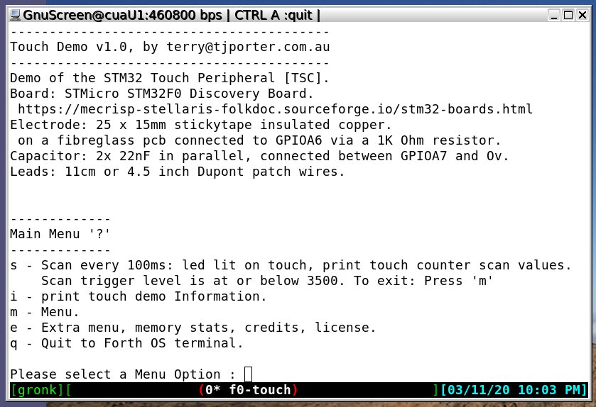
STM32 TOUCH SENSOR (TSC) DEMO BINARY
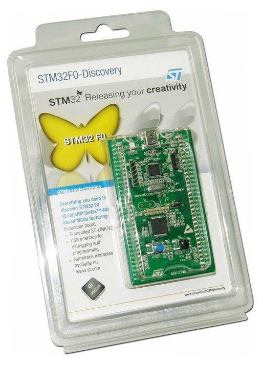
This project supplies a binary file ready to run on a STM32F0 Discovery Board. It provides a fully configured Touch Sensor and Menu so that various user created touch sensors may be tested and calibrated.
NEW! Download this project in a tarball with everything, including sourcecode, binary, readme etc.
My new Tarball Release format contains everything you need to develop this project.
Download the OLD binary only: https://sourceforge.net/projects/mecrisp-stellaris-folkdoc/files/STM32F0-Discovery-TouchSensor-Demo.bin
STM Technical Manual Description
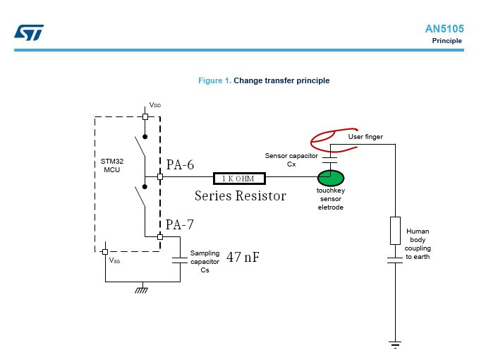
The touch sensing controller provides a simple solution for adding capacitive sensing functionality to any application. Capacitive sensing technology is able to detect finger presence near an electrode which is protected from direct touch by a dielectric (for example glass, plastic). The capacitive variation introduced by the finger (or any conductive object) is measured using a proven implementation based on a surface charge transfer acquisition principle.
Schematic
Figure 1. modified with the component values and GPIO Pins I have used in this project.
Documentation
STM32F051 Technical Manual: RM0091
Getting started with touch sensing control on STM32 microcontrollers: AN5105
Mecrisp-Stellaris Forth: This site!
Instructions
Download the binary and flash it to your F0 Discovery board.
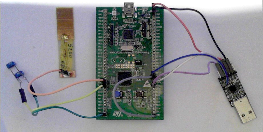
Connect a serial terminal as shown in the wiring chart below
Connect the 47 nF capacitor and a touch pad of some kind. A coin with a wire attached and wrapped in stickytape should work fine.
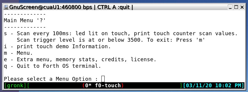
When the board is powered up you should see the ‘Main Menu’. If not, enter “?” to start the menu.
Select ‘s’ and scanning should begin ready for touch experiments.
Connection Information
STM32F0 Discovery Board
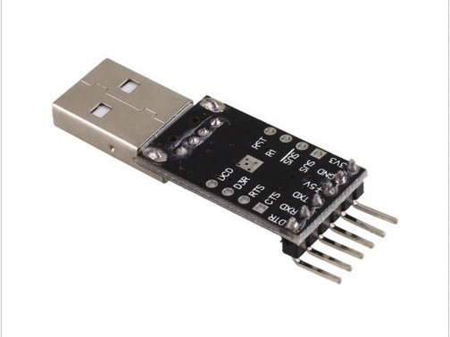
USB-3.3 Volt Dongle
Wiring
Wiring Chart
STM32F0 Discovery |
Description |
USB-3.3v dongle |
47nF Capacitor |
Electrode |
|---|---|---|---|---|
+5V (input) |
+5 volts |
+5V (output) |
||
GND |
0 volts |
GND |
||
PA9 (TX) |
serial data |
RX |
||
PA10 (RX) |
serial data |
TX |
||
PA11 (CTS) |
handshaking |
RTS (not used) |
||
PA12 (RTS) |
handshaking |
CTS |
||
PA7 |
47 nf Cap |
|||
GND |
47 nf Cap |
|||
PA6 |
Electrode |
Notes
The ELECTRODE has only ONE wire
The 47 nanoFarad capacitor is non-polarised
Serial
460800 baud, N,1
Handshaking isn’t essential if you only want to read data from the board (test different electrodes etc). It’s only ESSENTIAL if you want to upload Forth Source.
CTS/RTS handshaking works but isn’t needed so PA11 can connect to GND instead of the USB-3.3v dongle if you like. DON’T leave PA11 FLOATING or serial comms won’t work!
Development Binary Menu
Main Menu
Information Menu
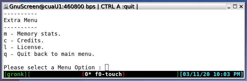
Extra Menu
The menu contains most of the functions one needs to test various capacitive sensor designs including the ‘counter’ values which change with sensor size,shape and touch.
A LED on the Discovery Board also lights when a finger ‘press’ is detected.
Touchkey Sensor Electrodes
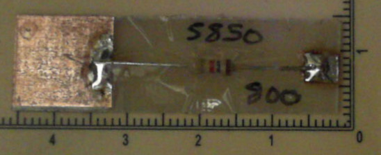
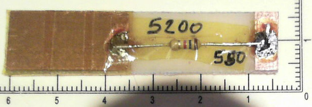
These are some of my prototypes made from single sided copper coated scrap pcb material.
Touch Pad Stats
All pads are insulated by tape (even if it isn’t visible), the finger can’t electrically touch anything.
PCB Number |
PCB Material |
Insulation |
Untouched |
Touched |
Signal/Noise Ratio |
|---|---|---|---|---|---|
1 |
Teflon Composite |
stickytape |
5390 |
500 |
10.8 |
2 |
Fibreglass |
stickytape |
5850 |
800 |
10.8 |
3 |
Fibreglass |
Kapton |
5200 |
550 |
9.45 |
Note
The use of Kapton resulted in slightly less signal/noise ratio. touched = finger firmly pressing on the copper pad. Scale shown in pictures is in mm
#1 Teflon Composite
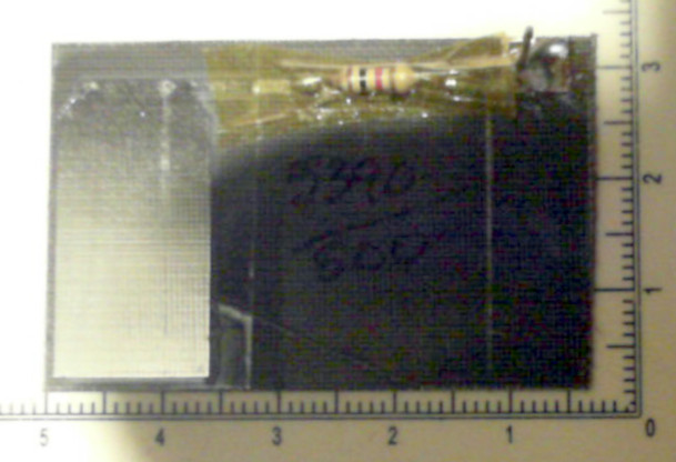
#2 Fibreglass
Insulation: stickytape
#3 Fibreglass
Insulation: Kapton
Fault Outputs
No Electrode connected
“s” output:
9235
9235
9240
9235
9238
9239
9234
9236
9236
No Capacitor connected
“s” output:
1 *
1 *
1 *
1 *
1 *
1 *
1 *
No Capacitor or Electrode connected
“s” output:
1 *
1 *
1 *
1 *
1 *
1 *
1 *
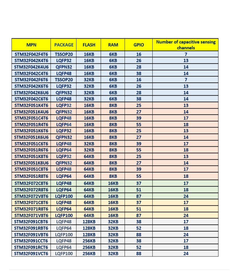
The TSC Peripheral
This peripheral is available on many STM32F/L0, and STM32F/L4’s but not all STM’s including the STM32F1xx, eg the ‘Blue Pill’. The table below lists the number of touch sensors available on various STM32F models.
Summary
Initially I thought that the TSC results might be a bit flaky or not work at all on a standard low cost “F0 Discovery” board where the lead capacitances are ‘whatever’ and there is a lot of electrical noise.
I couldn’t have been more wrong! Instead I found that the TSC is highly robust and repeatable. I intend to use it in further projects, some of which I only saw the possibilities after playing with this kit.
For Developers
Binary, Brief Description
This project uses Mecrisp-Stellaris Forth on a FO Discovery Board containing a STM32F051 MCU overclocked to 75 MHz (via the Disco 8MHz xtal) and running a simple task scheduler consisting of Task 1 which occurs every 100 milliseconds and triggers a TSC ‘acquisition’ interrupt. Five milliseconds after the acquisition, Task 2 runs displaying the results.
The controlling serial terminal response is the same whether scanning or not.
After quitting out of the menu, the Forth system is available, type “words4” to see a list of all the Words (subroutines) available in the binary.
Interesting Words
gpioa.
rcc.
free
nvic.
2 2 + .
200 200 * .
0 207 0 305 f/ f.
.” Hello World” cr
green-on
green-off
Development History
Developing this Forth bootable binary took a few days as I attempted to learn about the TSC peripheral, understand the STMicro TSC configuration ‘C’ code example and port it to Forth whilst testing on a STMicro F0 Discovery board.
Whilst very helpful, the ‘code example’ is incomplete because it doesn’t contain enough information to actually build a working prototype. This may explain why there are so few projects using the STM32 TSC on the Internet?
STMicro C TSC code example
Copied from the “STM32F0x1/STM32F0x2/STM32F0x8 advanced ARM®-based 32-bit MCUs Reference Manual RM0091” dated January 2017.
A.18.1  TSC configuration code example

        /* Configure TCS */
        /* With a charge transfer around 2.5 µs */
        /* (1) Select fPGCLK = fHCLK/32,
          Set pulse high = 2xtPGCLK,Master
          Set pulse low = 2xtPGCLK
          Set Max count value = 16383 pulses
          Enable TSC */
        /* (2) Disable hysteresis */
        /* (3) Enable end of acquisition IT */
        /* (4) Sampling enabled, G2IO4 */
        /* (5) Channel enabled, G2IO3 */
        /* (6) Enable group, G2 */
        TSC->CR = TSC_CR_PGPSC_2 | TSC_CR_PGPSC_0 | TSC_CR_CTPH_0 | TSC_CR_CTPL_0 | TSC_CR_MCV_2 | TSC_CR_MCV_1 | TSC_CR_TSCE; /* (1) */
        TSC->IOHCR &= (uint32_t)(~(TSC_IOHCR_G2_IO4 | TSC_IOHCR_G2_IO3)); /* (2) */
        TSC->IER = TSC_IER_EOAIE; /* (3) */
        TSC->IOSCR = TSC_IOSCR_G2_IO4; /* (4) */
        TSC->IOCCR = TSC_IOCCR_G2_IO3; /* (5) */
        TSC->IOGCSR |= TSC_IOGCSR_G2E; /* (5) */

A.18.2 TSC interrupt code example

        /* End of acquisition flag */
        if ((TSC->ISR & TSC_ISR_EOAF) == TSC_ISR_EOAF)
        {

           TSC->ICR = TSC_ICR_EOAIC; /* Clear flag */
           AcquisitionValue = TSC->IOGXCR[1]; /* Get G2 counter value */
        }
What’s Missing From The C Code Example?
GPIO Alternate Function selection code. Touch requires a minimum of two GPIO pins to be useful.
Starting an ‘acquisition’ by setting the ‘START’ BIT (1) of TSC_CR. Without this, nothing happens!
A more recent STMicro ‘Touch Sensor’ example I found was a series of GUI window pictures using Eclipse, HAL and STM32cube etc. There was no real code in this article, is this the dumbed-down future of embedded design?
Forth Code
This code excerpt from the touch demo binary shows the TSC peripheral config and interrupt code.
8 bit constant TSC-INTERRUPT  \ bitposn 8 settable TSC  Touch sensing interrupt
0 variable task1-time
0 variable task1b-flag
6000 variable g2-counter
0 variable touched-flag
2500 variable sensitivity

\ ------------------------------------- Config Words ------------------------------------------- \
: RCC_AHBENR_TSCEN ( -- x addr ) 24 bit RCC_AHBENR ; \ RCC_AHBENR_TSCEN, Touch sensing controller clock  enable
: NVIC_ISER_SETENA ( %bbbbbbbbbbbbbbbbbbbbbbbbbbbbbbbb -- x addr ) NVIC_ISER ; \ NVIC_ISER_SETENA, SETENA
: GPIOA_AFRL_AFRL7   ( %bbbb -- x addr ) 28 lshift GPIOA_AFRL ; \ GPIOA_AFRL_AFRL7, Alternate function selection
: GPIOA_AFRL_AFRL6   ( %bbbb -- x addr ) 24 lshift GPIOA_AFRL ; \ GPIOA_AFRL_AFRL6, Alternate function selection
: GPIOA_MODER_MODER7 ( %bb -- x addr ) 14 lshift GPIOA_MODER ; \ GPIOA_MODER_MODER7
: GPIOA_MODER_MODER6 ( %bb -- x addr ) 12 lshift GPIOA_MODER ; \ GPIOA_MODER_MODER6,
: TSC_CR_TSCE  ( -- 1 addr ) 0 bit TSC_CR ; \ TSC_CR_TSCE, Touch sensing controller enable
: TSC_CR_START ( -- x addr ) 1 bit TSC_CR ; \ TSC_CR_START, Start a new acquisition
: TSC_CR_MCV   ( %bbb -- x addr ) 5 lshift TSC_CR ; \ TSC_CR_MCV, Max count value
: TSC_CR_PGPSC ( %bbb -- x addr ) 12 lshift TSC_CR ; \ TSC_CR_PGPSC, pulse generator prescaler
: TSC_CR_CTPH  ( %bbbb -- x addr ) 28 lshift TSC_CR ; \ TSC_CR_CTPH, Charge transfer pulse high
: TSC_CR_CTPL  ( %bbbb -- x addr ) 24 lshift TSC_CR ; \ TSC_CR_CTPL, Charge transfer pulse low
: TSC_IOHCR_G2_IO4 ( -- x addr ) 7 bit TSC_IOHCR ; \ TSC_IOHCR_G2_IO4, G2_IO4 Schmitt trigger hysteresis  mode
: TSC_IOHCR_G2_IO3 ( -- x addr ) 6 bit TSC_IOHCR ; \ TSC_IOHCR_G2_IO3, G2_IO3 Schmitt trigger hysteresis  mode
: TSC_IER_EOAIE    ( -- 1 addr ) 0 bit TSC_IER ; \ TSC_IER_EOAIE, End of acquisition interrupt  enable
: TSC_IOSCR_G2_IO4 ( -- x addr ) 7 bit TSC_IOSCR ; \ TSC_IOSCR_G2_IO4, G2_IO4 sampling mode
: TSC_IOCCR_G2_IO3 ( -- x addr ) 6 bit TSC_IOCCR ; \ TSC_IOCCR_G2_IO3, G2_IO3 channel mode
: TSC_IOGCSR_G2E   ( -- x addr ) 1 bit TSC_IOGCSR ; \ TSC_IOGCSR_G2E, Analog I/O group 1 enable
: TSC_ICR_EOAIC    ( -- 1 addr ) 0 bit TSC_ICR ; \ TSC_ICR_EOAIC, End of acquisition interrupt clear
: TSC_IOG2CR_CNT?  ( %bbbbbbbbbbbbbb -- x ) TSC_IOG2CR @ ; \ TSC_IOG2CR_CNT, Counter value
\ ------------------------------------- Config Words ------------------------------------------- \

: tsc-config ( -- ) \ Init and configure the TSC peripheral ready for use
  RCC_AHBENR_TSCEN bis!

  \ GPIO: Alternate Function Mode: PA6 & PA7
  AF GPIOA_MODER_MODER7 bis!
  AF GPIOA_MODER_MODER6 bis!

  \ GPIO: AF3: PA6 & PA7
  AF3 GPIOA_AFRL_AFRL6 bis!  \ PA6 = TSC_G2_IO3
  AF3 GPIOA_AFRL_AFRL7 bis!  \ PA7 = TSC_G2_IO4

  \ 1. CONFIGURE TCS With a charge transfer around 2.5 µs
  %101 TSC_CR_PGPSC bis!  \ a. Select fPGCLK = fHCLK/32, 101: fHCLK /32
    %1 TSC_CR_CTPH bis!   \ b. Set pulse high = 2xtPGCLK,Master. CTPH: 0001: 2x tPGCLK
    %1 TSC_CR_CTPL bis!   \ c. Set pulse low = 2xtPGCLK. CTPL: 0001: 2x tPGCLK
  %110 TSC_CR_MCV  bis!   \ d. Set Max count value = 16383 pulses. 110: 16383
       TSC_CR_TSCE bis!   \ e. Enable TSC. TSC_CR_TSCE, Touch sensing controller enable

  \ 2. DISABLE HYSTERESIS 0: Schmitt trigger hysteresis disabled
       TSC_IOHCR_G2_IO4 bic! \ disable G2_IO4 Schmitt trigger hysteresis
       TSC_IOHCR_G2_IO3 bic! \ disable G2_IO3 Schmitt trigger hysteresis

  \ 3. ENABLE END OF ACQUISITION INTERRUPT
       TSC_IER_EOAIE bis! \  End of acquisition interrupt enable

  \ 4. SAMPLING ENABLED, G2IO4. 1: G2_IO4 used as sampling capacitor
  \ These bits are set and cleared by software to configure the G2_IO4 as a sampling capacitor
  \ I/O. Only one I/O per analog I/O group must be defined as sampling capacitor.
       TSC_IOSCR_G2_IO4 bis! \ G2_IO4 = sampling mode

  \ 5. CHANNEL ENABLED, G2IO3. 1: G2_IO3 used as channel
       TSC_IOCCR_G2_IO3 bis! \ G2_IO3 = channel mode

  \ 6. ENABLE GROUP, G2.
       TSC_IOGCSR_G2E bis!   \ TSC_IOGCSR_G2E = Analog I/O group
;

: g2-counter? ( -- x ) g2-counter @ ; \ This is the value of the sensor read, high values around 5000 mean no touch

: acquire ( --  )      \ TSC_CR_START, Start a new acquisition
   TSC_CR_START bis!   \ start acquisition, it finishes with a interrupt by the irq-tsc
;                      \ which updates g2-counter within about 5 milliseconds.

: tsc-handler ( -- )   \ Interrupt occurs because voltage across CS has reached the threshold
  TSC_ICR_EOAIC bis!   \ TSC_ICR_EOAIC,  Clear "End of acquisition interrupt flag"
  TSC_IOG2CR_CNT?  g2-counter ! \ count = number of charge transfer cycles generated to complete acquisition
;

: tsc-init ( -- )
  ['] tsc-handler irq-tsc !         \ tie handler to interrupt
  TSC-INTERRUPT NVIC_ISER_SETENA !  \ enable TSC interrupt
;
