Project: LMT01 Temperature Sensor
This project displays up to three LMT01 temperature sensor readings in degrees C/F, reading one sensor at a time. The design allows for one LMT01 sensor per GPIO pin, and more can be easily added.
Example Output
testall ( only LMT01 sensors 1 and 2 are fitted )

Sensor-1: 25.5C or 77.9F
Sensor-2: 25.4C or 77.7F
Sensor-3: LMT01 faulty or disconnected
Sensor-4: No such sensor !!  ok.
YouTube Video
The LMT01 Temperature Sensor
The LMT01 provides a digital output in the form of a pulse count that is transmitted by a train of current pulses.
After the LMT01 is powered up, it transmits a very low current of 34 µA for less than 54 ms while performing a temperature to digital conversion. When the temperature-to-digital conversion is complete, the LMT01 transmits a pulse train that toggles from the low current of 34 µA to a high current level of 125 µA.
The total pulse count represents the temperature of the LMT01.
LMT01 Spec
The LMT01 outputs at minimum 1 pulse and a theoretical maximum of 4095 pulses. Each pulse has a weight of 0.0625°C.
One pulse corresponds to a temperature less than -50°C while a pulse count of 4096 corresponds to a temperature greater than 200°C.
Warning
The LMT01 is only ensured to operate up to 150°C. Exceeding this temperature by more than 5°C may damage the device. The accuracy of the device degrades as well when 150°C is exceeded.
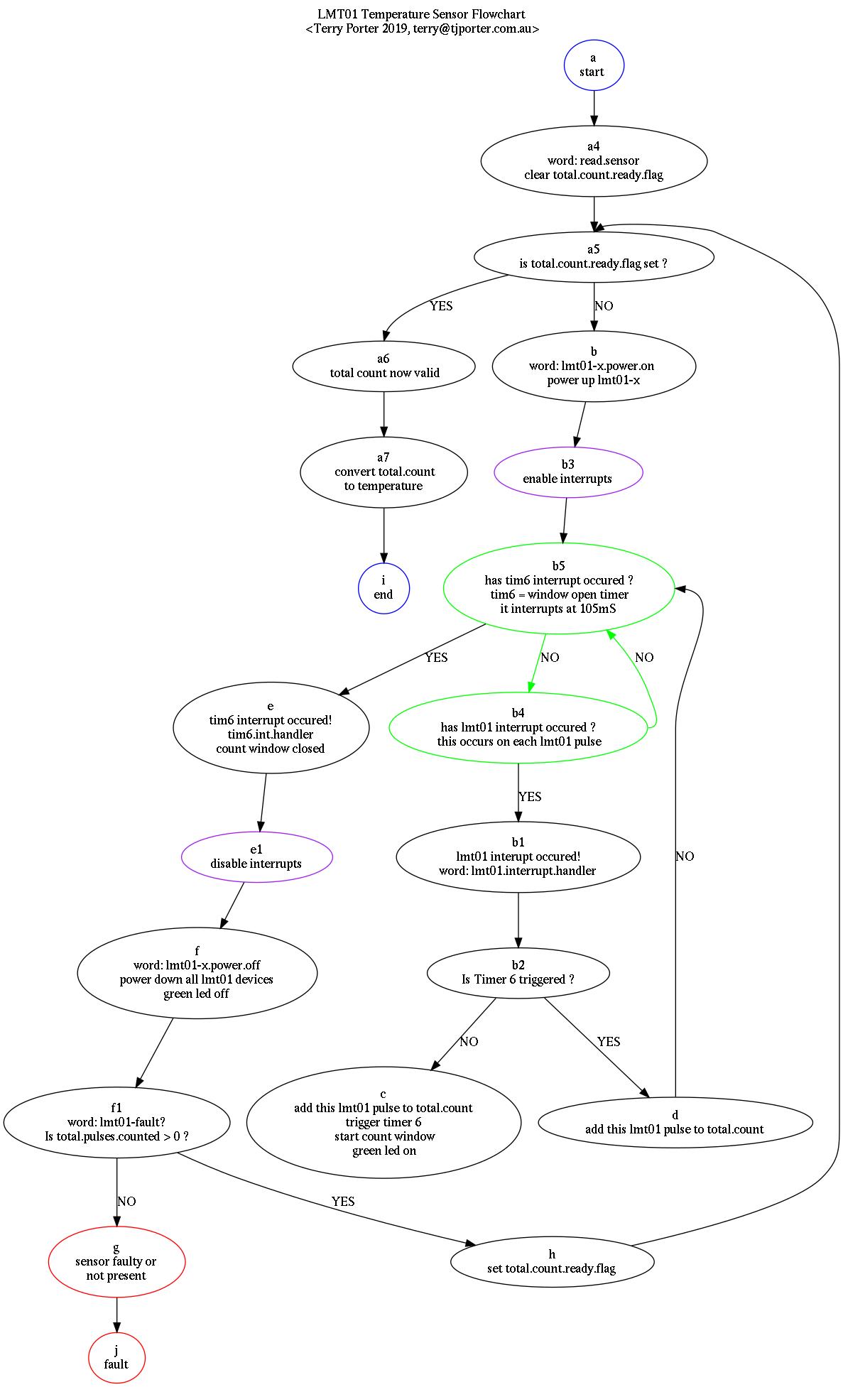
Software Flowchart
This is the basic design of the Forth software to read multiple LMT01 two wire temperature sensors. My next modification will be to count the pulses from the temperature sensors in a counter timer so the MCU doesn’t need to do it (currently handled by interrupts), freeing up cpu cycles for more important tasks.
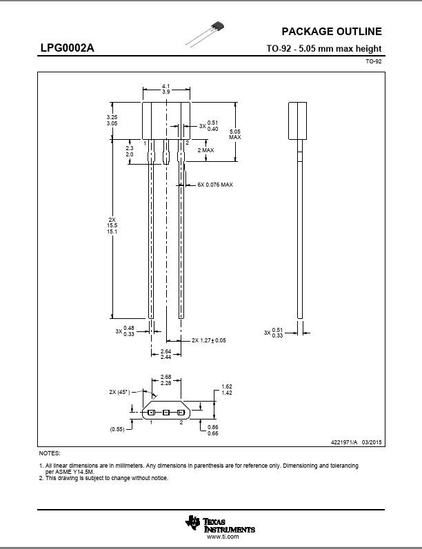
LMT01 TO-92 Package
LMT01 Waveforms
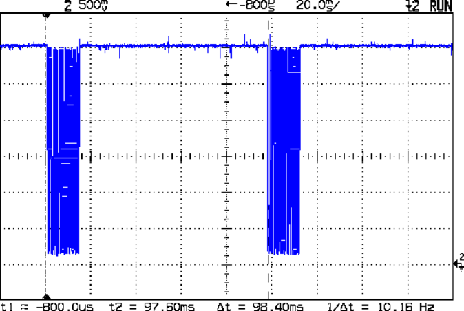
Free Running Pulse Block Timing
Taken at the Collector of Q1
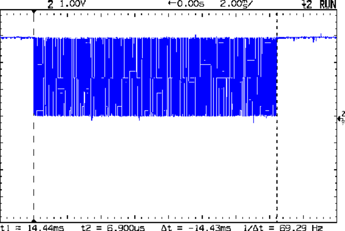
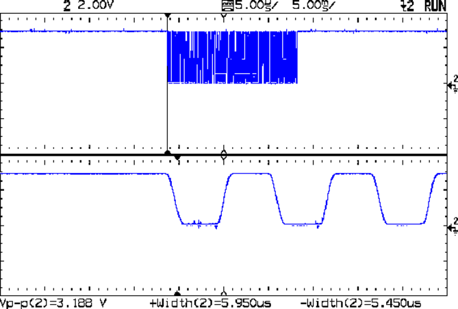
Pulse Block Width
Taken at the Collector of Q1
Individual Pulse Timing
Taken at the Collector of Q1
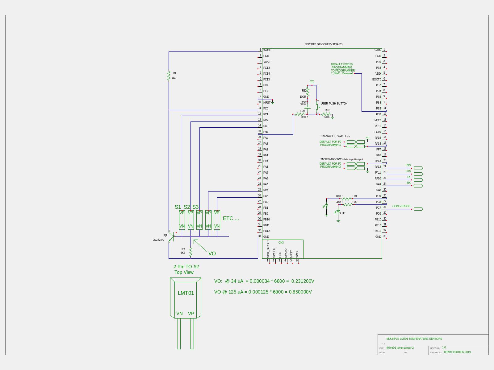
The schematic
Note
all parts inside the STM32F0 Discovery Board rectangle are actually built into it by ST, they aren’t parts I’ve added for this project
LMT01 Software
This is actually one file f0-lmt01-temp-sensor-2.fs but I’ve broken it up into three parts for clarity. If you copy and paste these files, just load part-1 first, part-2 second, and part-3 third.
Part-2
This is the ‘main’ program which counts the temperature sensor pulses, scales and prints the results.
: lmt01-fault? ( -- ) raw.temperature @ 0 = ;        \ If a sensor has a zero count, it's faulty
: pretty.print ( -- )  0 <# # 46 hold #s #> type  ;  \ Insert one decimal point into final value

: degrees.c ( raw -- C )  \ Print Degrees C
  pretty.print ." C "
;

: degrees.f ( raw -- F )  \ Convert Degrees C to Degrees F  (formula: °C  x  9/5 + 32 = °F
   90 5 / * 3200 + 10 /
   pretty.print ." F "
;

: degrees ( -- )
     lmt01-fault? if ." LMT01 faulty or disconnected "
        else
        raw.temperature @                      \ fetch total number of pulses counted
        10000 4096 */ 256 * 500000 - 1000 /    \ Temp (C) = ((count/4096) *256) -50 scale raw temp into degrees x 10
        dup degrees.c ." or " degrees.f
     then
;

: temperature? ( sensor -- )             \ one temperature? measurement
  0 lmt01-x.count !                      \ lmt01-x.count increments once per lmt01-x pulse
  0 raw.temperature !                    \ raw.temperature is lmt01-x.count total count
  0 ready.flag !                         \ ready.flag is set when raw.temperature value is stable and ready to be used
     case                                \ power up selected sensor
        1 OF lmt01-1.power.on ENDOF
        2 OF lmt01-2.power.on ENDOF
        3 OF lmt01-3.power.on ENDOF
        ." No such sensor !! " drop exit         \ sensor not implimented fall thru warning
     endcase
  green-on                               \ mark start of count window
  tim6_cr1_cen                           \ start timer6 (end of timer kills the power to the lmt01)
     begin                               \ loop until raw.temperature is stable
        pause
        ready.flag @ 1 =
     until
  degrees cr
;

: t temperature? ;

: testall cr ( -- ) \ simple test of sensors
  ." Sensor-1: " 1 t
  ." Sensor-2: " 2 t
  ." Sensor-3: " 3 t
  ." Sensor-4: " 4 t
;
Part-1
Contains all the low level routines, variables and constants
compiletoram

0 variable lmt01-x.count
0 variable raw.temperature
0 variable ready.flag

\ RCC Words
: rcc_apb2enr_syscfgen-set ( -- )  %1  0  lshift  rcc_apb2enr bis! ;   \ rcc_apb2enr_syscfgen syscfg clock enable
: rcc_apb1enr_tim6en ( -- ) %1 4 lshift rcc_apb1enr bis! ;             \ rcc_apb1enr_tim6en tim6 clock enable

: init.gpio ( -- )
  \ One Port pull up for all sensors
  rcc_apb2enr_syscfgen-set   \ REQUIRED!! for using GPIO's as interrupts!
  pull-up ( %xx -- ) 0 lshift gpioc_pupdr bis!  \ gpioc_pupdr_pupdr0 PC0
;

\ LMT01 related Words
: syscfg_exticr1_exti0 ( -- ) %0010  0  lshift  syscfg_exticr1 bis! ;  \ pc-0 is interrupt source  x010: pc[0] pin
: exti_imr_mr0-set ( -- )  %1  0  lshift  exti_imr bis! ;              \ exti_imr_mr0 set interrupt mask on line 0
: exti_pr_pr0 ( -- ) %1 0 lshift exti_pr bis! ;                        \ exti_pr_pr0    pending bit 0
: exti_ftsr_tr0-set ( -- )  %1  0  lshift  exti_ftsr bis! ; \ exti_ftsr_tr0 falling trigger event configuration of  line 0
: exti_pr_pr0-set ( -- )  %1  0  lshift exti_pr  bis! ;                \ exti_pr_pr0 interrupt pending flag for line 0
: nvic_iser_setena-exti0_1 ( -- )  %100000 0  lshift nvic_iser  bis! ; \ nvic_iser_setena-exti0_1
: nvic_icer_clrena-exti0_1 ( -- )  %100000 0  lshift nvic_icer  bis! ; \ nvic_icer_clrena-exti0_1

: lmt01-1.power.on  ( -- )
  output  ( %xx -- ) 2 lshift gpioc_moder bis!    \ gpioc_moder_moder1  PC1
  %1 1 lshift gpioc_bsrr bis!                     \ gpioc_bsrr_bs1; output high
;

: lmt01-2.power.on  ( -- )
  output ( %XX -- ) 4 lshift GPIOC_MODER bis!     \ GPIOC_MODER_MODER2  PC2
  %1 2 lshift gpioc_bsrr bis! ;                   \ gpioc_bsrr_bs2; output high


: lmt01-3.power.on  ( -- )
  output ( %XX -- ) 6 lshift gpioc_moder bic!     \ gpioc_moder_moder3  PC3
  %1 3 lshift gpioc_bsrr bis! ;                   \ gpioc_bsrr_bs3; output high


: lmt01-1.power.off %11 ( -- ) 2 lshift gpioc_moder bic! ; \ gpioc_moder_moder1  PC1
: lmt01-2.power.off %11 ( -- ) 4 lshift gpioc_moder bic! ; \ gpioc_moder_moder2  PC2
: lmt01-3.power.off %11 ( -- ) 6 lshift gpioc_moder bic! ; \ gpioc_moder_moder3  PC3

: lmt01-x.power.off ( -- ) \ turn off all lmt01's by switching the port from output to input mode
  lmt01-1.power.off
  lmt01-2.power.off
  lmt01-3.power.off
;

\ Tim6 related Words
48000000 constant fCK

: nvic_iser_setena-tim6 ( -- ) 1 17 lshift nvic_iser bis! ;     \ nvic_iser_setena   tim6
: nvic_icer_clrena-tim6 ( -- ) 1 17 lshift nvic_icer bis! ;     \ nvic_icer_clrena  tim6
: nvic_icpr_clrpend-tim6 ( -- ) 1 17 lshift nvic_icpr bis! ;    \ nvic_icpr_clrpend  tim6
: tim6_cnt@ ( -- ) tim6_cnt h@ ;  \ tim6_cnt_cnt   16 bit counter value
: tim6_cr1_opm ( -- ) %1 3 lshift tim6_cr1 hbis! ;      \ tim6_cr1_opm one-pulse mode
: tim6_cr1_cen ( -- ) %1 0 lshift tim6_cr1 hbis! ;      \ tim6_cr1_cen    counter enable
: tim6_cr1_cdis ( -- ) %1 0 lshift tim6_cr1 hbic! ;     \ tim6_cr1_cen    counter disable
: tim6_dier_uie ( -- ) %1 0 lshift tim6_dier hbis! ;    \ tim6_dier_uie        update interrupt enable
: tim6_sr_uif ( -- ) %1 0 lshift tim6_sr hbic! ;        \ tim6_sr_uif  clear tim6 int pending flag
: tim6_egr_ug ( -- ) %1 0 lshift tim6_egr hbis! ;       \ tim6_egr_ug  update generation

: preset.psc.no.int ( -- ) \ preset Prescaler but don't cause interrupt. PSC does not get 'active' until the second update event
  tim6_arr h!              \ preset arr
  tim6_egr_ug              \ update generation: (causes a interrupt when run) but loads ARR into shaddow register!
  tim6_sr_uif              \ clear tim6 int pending flag after running tim6_egr_ug
  tim6_dier_uie            \ update interrupt enable
;

: tim6.int.handler ( -- )
  nvic_icpr_clrpend-tim6              \ clear pending iser for tim6
  tim6_sr_uif                         \ clear tim6 int pending flag
  tim6_cr1_cdis                       \ counter disable
  nvic_icer_clrena-tim6               \ disable the tim6 interrupt or dropping power to the LMT01 will re-trigger it
  green-off                           \ mark finish of count window
  lmt01-x.power.off
  lmt01-x.count @ raw.temperature !   \ raw.temperature now contains valid lmt01 count
  1 ready.flag !                      \ it's safe to read raw.temperature now
  nvic_iser_setena-tim6               \ re-enable tim6 iser
  nvic_iser_setena-exti0_1            \ re enable exti0_1 iser ( won't work without this )
;

: init.tim6 ( -- )
  rcc_apb1enr_tim6en      \ enable tim6 in rcc
  tim6_cr1_opm            \ one pulse mode high = Counter stops counting at the next update event (clearing the bit CEN)
  47952 tim6_psc h!       \ preset prescaler for 1mS (47 for 1 uS)
  104 preset.psc.no.int   \ preset PSC --> clear int pending flag, enable interrupt
  ['] tim6.int.handler irq-tim6_dac !
  nvic_iser_setena-tim6   \ enable iser
;

: lmt01.interrupt.handler ( -- )
  exti_pr_pr0                         \ clear pending bit 0
  lmt01-x.count @ 1+ lmt01-x.count !  \ increment temperature count by one
  exti_pr_pr0-set                     \ clear external interrupt pending register (exti_pr)
;

: init.lmt01 ( -- )
  syscfg_exticr1_exti0                         \ negative going pulses from lmt01 trigger pc0 interrupt
  exti_imr_mr0-set                             \ exti0 set interrupt mask on line 0
  exti_ftsr_tr0-set                            \ falling trigger on line 0
  ['] lmt01.interrupt.handler irq-exti0_1 !    \ tie the interrupt handler to the interrupt
  nvic_iser_setena-exti0_1                     \ enable exti0_1 interrupt
;
Part-3
This last part adds initialization and multitasking
: main ( -- )                \ executed about every 5ms @48mHz
 pause
;

: init-general ( -- )        \ executed once at boot-up
  f0-disco-48mhz             \ switch MCU clock from 8 to 48 MHz
  init.gpio                  \ Initialisations
  init.tim6
  init.lmt01
;

task: maintask         \ essential multitasking Word
: main& ( -- )          \ multitasking.fs Word
  maintask activate    \ multitasking.fs Words
  begin main again     \ this is the only task, and it loops forever (about every 5uS @ 48Mhz clock) unless blocked
;

: init ( -- )        \ essential multitasking Word
  init-general      \ main user application inits
  multitask         \ multitasking.fs Word
  main&             \ multitasking.fs Word
;

init                 \ this init for non flash use, i.e. after uploading this program
Waveforms
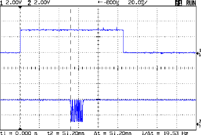
Window Start to Pulse Block Start Timing
Window and Power are the same thing displayed on CH-1
Waveform 1: PC-1
Waveform 2: Collector Q1
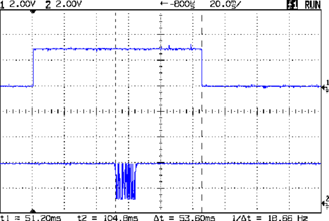
Pulse Block Start to Window Close Timing
Waveform 1: PC-1
Waveform 2: Collector Q1
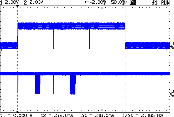
Testall
Waveform 1: PC-1
Waveform 2: Collector Q1
Downloads
screen-f0-lmt01-temp-sens~2-cuaU0-498600-ctsrts.sh
Kernel be337881895e64e60016a3514a0dea8e.bin
be337881895e64e60016a3514a0dea8e.words.txt
be337881895e64e60016a3514a0dea8e.README.txt
Note
The Kernel binary filename is a MD5SUM of the file itself.
md5 be337881895e64e60016a3514a0dea8e.bin
MD5 (be337881895e64e60016a3514a0dea8e.bin) = be337881895e64e60016a3514a0dea8e
